28
COMMUNICATIONS INTERFACE PORT
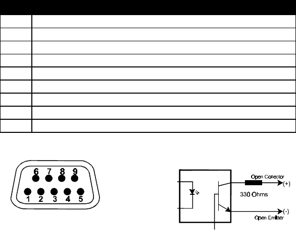
The UPStation GXT UPS contains a standard DB-9 socket located on the rear of
the UPS unit. Several signals are provided on this port and are assigned as
follows:
PIN ASSIGNMENT DESCRIPTION
1 Low Battery (open collector)
2 UPS TxD (typical RS-232 levels)
3 UPS RxD (typical RS-232 levels)
4 Remote Shutdown (5-12V); battery operation
5 Common
6 Remote Shutdown (short to pin 5); any mode
7 Low Battery (open emitter)
8 Utility Fail (open emitter)
9 Utility Fail (open collector)
PIN ASSIGNMENT COLLECTOR TO EMITTER*
*Maximum voltage and current on pins 1,7,8,9 is 80V DC; 10.0 mA.
CAUTION: TO MAINTAIN SAFETY (SELV-Safety Extra Low Voltage)
BARRIERS AND FOR ELECTROMAGNETIC COMPATIBILITY, SIGNAL
CABLES SHOULD BE SEGREGATED AND RUN SEPARATE FROM ALL
OTHER POWER CABLES, BY 1inch (25mm) WHERE APPLICABLE.


