26
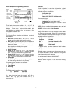
Power Management Programming Elements
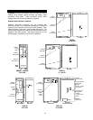
Loads
These Load selections are available: 1, 2, 3, 4, 5, 6, 7, 8,
All. A ”load” as referenced in this section is the Load
Module. Since some load modules contain two
receptacles, both receptacles are considered one ”load”.
Load Modules are numbered from top to bottom in the
Configurable Distribution unit.
Events
The following Event selections (schedule or conditions)
are available:
• Day Time: Individual days, All, M-F, and S-S. Time is
based on 24 hour clock, and then to the minute.
• Date Time: Month and Day (avoid invalid dates such
as FEB 30). Time is based on 24 hour clock, and
then to the minute.
• Batt Time Left: Based on UPS internal calculation
Note that this is not battery time elapsed.
• Utility Failed
• Utility Restored
• Outlet [X] ON: X can be 1 to 8. This event links
selected loads in the first line to the load selected
here. This link is ignored when in override mode.
• Outlet [X] OFF: X can be 1 to 8. This event links the
selected loads in the first line to the load selected
here. This link is ignored when in override mode.
• On Bypass
• Delete Entry: Deletes an entire program step (ignore
all other flashing selections for this process).
Actions
The following Action selections are available:
• Turn OFF load
• Turn ON load
• Warning
Delays
The following Delay selections are available:
S Seconds 00 to 99
M Minutes 00 to 99
If no delay is required, leave this selection as S with a
value of 00. The right arrow increases from 01 in
increments of 1. The left arrow decreases from 99 in
increments of 1.
Override
The Override selection causes immediate action to a load
module regardless of what was programmed. Linked
outputs are ignored during an override command. These
Override selections are available:
As Scheduled
Force Power OFF
Force Power ON
Reboot (OFF-ON) OFF for 30 seconds
The screen displays:
Load #X: Use right or left arrow to display 1 to 8
Load Label: See Load Labels section
As Scheduled: Use right or left arrow to select
option
NOTE: After an override, it is important to return the load
module to its current state (ON or OFF) via Force Power
ON/OFF, and then return it to As Scheduled.
Load Labels
Assign Load Labels of up to 16 characters. Some labels
are factory preprogrammed. Since UPS controls do not
provide an alphanumeric keyboard, use right or left arrow
to display a selection, then press enter to select. The
following selections are available:
Bridge Terminal
Computer No Label
Display Individual letters (A to Z)
Hub Individual numbers (0 to 9)
Modem Selected symbols
Router Blank space
Server
In applying labels, remember that some Load Modules
supply power to more than one device.
Operation
Selected program steps become active as soon as they
are entered Maintain a chart of selections. Change the
chart when you change the program.
For assistance call Liebert at 1-800-222-5877.
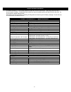
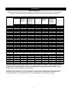
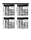
Sample Programs
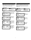
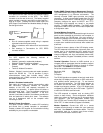
Refer to Sample Programs #1 and #2 on the following
pages.
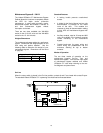
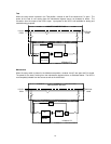
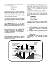
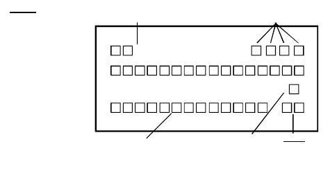
)LOAD
ACTION
DELAY
( )
#
,
,
,
Schedule Number
01 - 30
Load Numbers
1 - 8 or ALL
Action
Turn OFF Load
Turn ON Load
Warning
Time Base
S or M
Time
00 - 99
Event
Nothing Selected
Day
Date
Batt. Time Left
Utility Failed
Utility Restored
System Powerup
Outlet
Outlet
On Bypass
Delete Entry
Time
Time
[ ] ON
[ ] OFF


