3.5-6 kVA Start-up Checklist
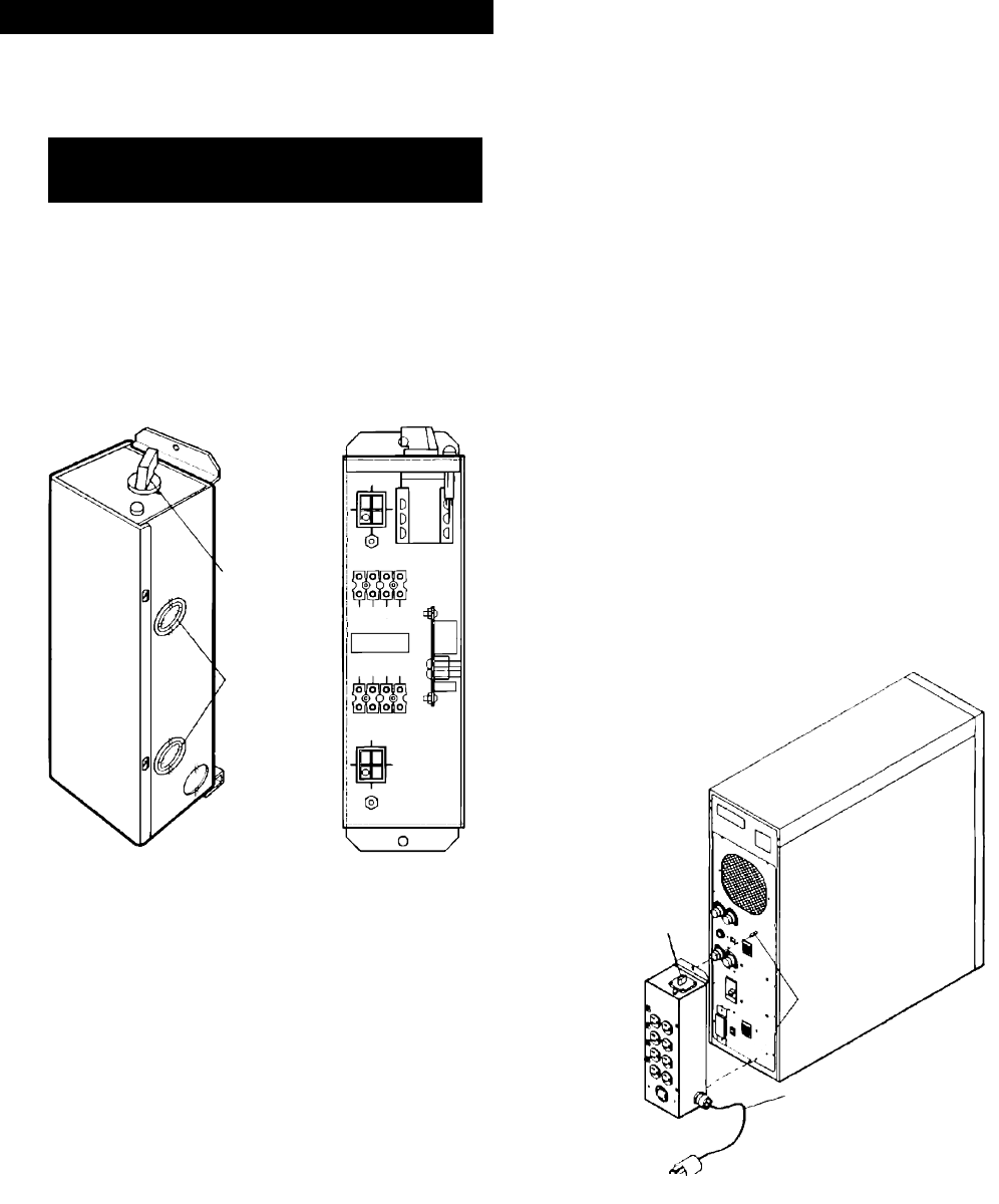
1. Remove POD from box. Set aside the two UPS
battery fuses inside the user manual packet for later
installation.
Steps 2 – 4 apply to UPS Hardwire Input / Output
connections ONLY.
For standard plug connections, skip to step 5.
2. Note conduit knockouts on unit side. Remove the
four screws securing the terminal block access cover.
3. Wire UPS input and/or output per NEC (NFPA 70)
and all applicable local codes. Use 75 degrees C
copper wire. See Site Planning Data and Table NEC
Wire Specifications in the Appendix. Note that
terminations used for an L-L-N-G system differ from
those used for an L-N-G system as indicated by the
terminal block labels below.
4. Reassemble the POD.
5. With UPS OFF, remove hex nuts on the two guide
pins on the rear of the UPS.
6. While holding the unit with the Maintenance Bypass
Switch on the top, guide the unit so that the UPS
guidepins insert in the holes at the top and bottom.
As the guidepins insert, ensure that the two sets of
connectors align. Once all the connector pins make
contact, push the unit onto the UPS until it is in
contact with the back of the UPS.
CAUTION: If connector pins do not align, DO NOT
force the unit onto the UPS. It may break the pins.
Instead, try to reinstall the unit.
7. Look at the connection from the side. There should
be no gap between the unit connectors and the UPS
connectors. If there is, push the unit further until no
gap exists. Thread hex nuts back onto guide pins
with a 7/1 6” wrench.
8. Verify the Maintenance Bypass Switch (switch SW2
on the unit) is in the ”UPS” position
9. Turn off all UPS-supported loads and plug them into
the POD.
10. Install the two battery fuses (F3 and F4). The second
fuse completes a circuit. The spark is a normal
indication.
11. Roll unit to final position. Allow at least one foot of
rear clearance. Adjust leveling feet.
12. Plug unit power cord into the wall outlet.
13. Turn ON customer-supplied wall outlet circuit breaker
to supply power to UPS control circuits. The fan and
the LCD display activate.
14. The LCD display prompts you to review and accept
default settings (see page 11) or configure the UPS
for your application.
15. After configuration, automatic self-tests begin. If self-
tests are OK, the Close Breaker then Press ON
message appears and an alarm sounds. Press Alarm
Silence Button to silence the alarm. If any other
message appears, contact Liebert at 1-800-222-5877.
16. Turn ON Output Circuit Breaker on back of UPS by
turning it OFF, then ON again to reset it. Press the
front panel ON button. The UPS tests the inverter
and displays the Normal Operation message.
17. Green light on unit indicates power available for loads
and normal UPS operation.
18. Turn on each critical load one at a time. The UPS
provides filtered, regulated power to protect valuable
processes and data.
Unit Installation
Maintenance
Bypass Switch
(SW2)
Input Plug
Guidepins
w/Hex Nuts
Terminal
Locations
Maintenance
Bypass Switch
(SW2)
Conduit
Knockouts
N
L1
G
L2
GND 1
G
G
L1
L1
L2
L2
N
N
CUSTOMER
CONNECTIONS
UPS INPUT
UPS OUTPUT
J2
UPS OUTPUT
GND 2
