


7
CASCADING
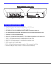
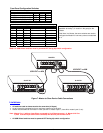
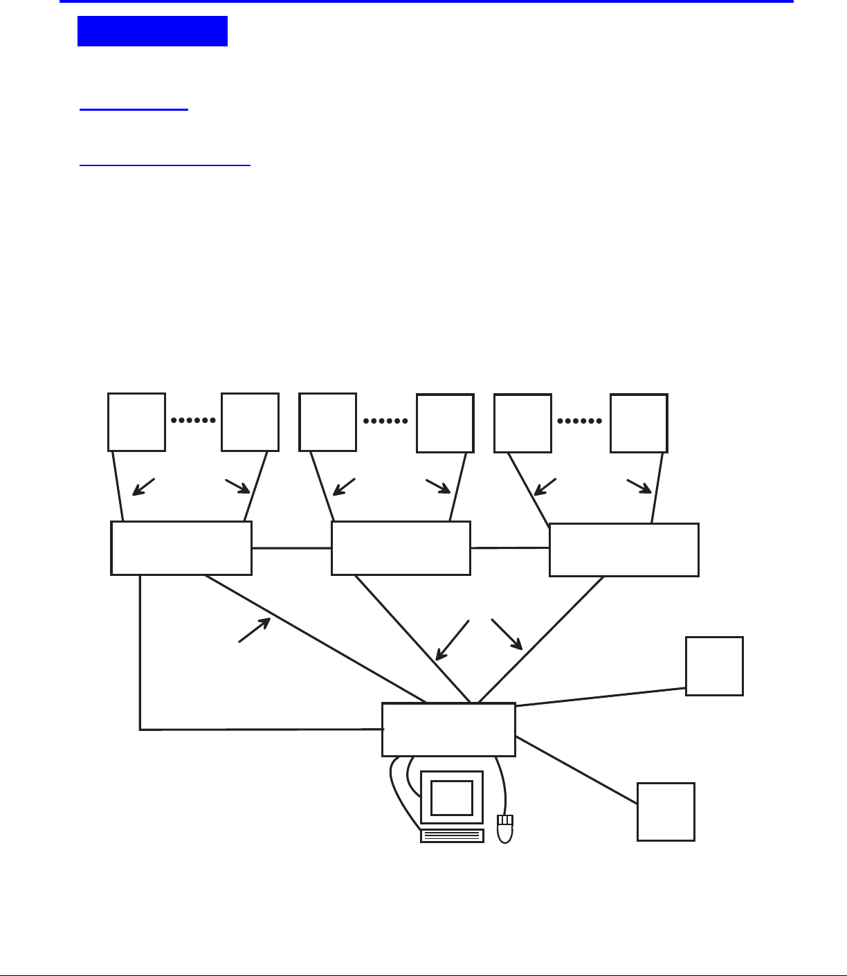
The USB Wizard can be cascaded as shown in Fig. 6 below. If USB Wizard switches are being cascaded, configure
the dip-switches accordingly (see Tables 1 and 2 on page 8).
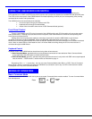
Configuration
All units are configured using the 6-position dip switch (located on the front of each unit) according to the tables on page 8 (1 & 2).
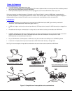
Cascaded Installation
a. Configure each dip switch as per the tables on page 8 before proceeding.
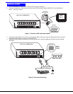
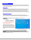
b. Using the 15HD video cable ends of a USBVEXT-xx-MM cable, connect the USB Wizard slave's MONITOR port to the master’s
VIDEO 1 port.
c. Using the USB ends of the same USBVEXT-xx-MM cable, connect one of the USB slave’s USB DEVICES ports to the
master’s CPU 1 port.
Note: Only one of the two ports labeled DEVICES on a slave needs to be used in order for cascading to work.
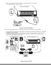
d. Repeat step b. & c. for each additional slave, keeping in mind that each slave will connect to the next available master’s
port (i.e. Slave #2 to master’s VIDEO 2 & CPU 2, etc.) See Fig. 7 on page 8.
e. With a RMT extension cable, connect the master’s DAISY OUT port to slave #2’s DAISY IN port. Then connect slave #2’s
DAISY OUT to slave #3's DAISY IN. Continue until all slaves are connected together.
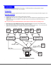
Figure 6- Connections for Cascading
.
CASCADING
( s l a v e u n i t 1 )
( s l a v e u n i t 2 )
( s l a v e u n i t 3 )
( m a s t e r u n i t )
R E X T - S R - x x
R E X T - S R - x x
R E X T - S R - x x
U S B - V E X T - x x M M
U S B V E X T - x x - M M
U S B
C P U
U S B
C P U
U S B
C P U
U S B
C P U
U S B
C P U
U S B
C P U
U S B
C P U
U S B
C P U
U S B V E X T - x x - M M
U S B V E X T - x x - M M
U S B V E X T - x x - M M
U S B - V E X T - x x M MU S B - V E X T - x x M M
USB Wizard USB Wizard USB Wizard
USB Wizard