TABLE OF FIGURES
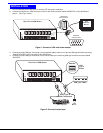
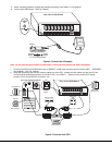
Figure 1- Connect a VGA multi-scan monitor .................................................................................................................4
Figure 2- Connect the device(s)......................................................................................................................................4
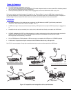
Figure 3- Connect the AC adapter ..................................................................................................................................5
Figure 4- Connect each CPU ..........................................................................................................................................5
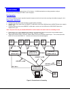
Figure 5- Compatible and incompatible device combinations.........................................................................................6
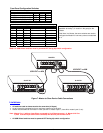
Figure 6- Connections for Cascading..............................................................................................................................7
Figure 7- Master-to-Slave Device Cable Connections....................................................................................................8
Figure 8- Administrator Login screen............................................................................................................................10
Figure 9- User Login screen..........................................................................................................................................11
Figure 10- Administration Mode menu..........................................................................................................................11
Figure 11- Administrator Password screen...................................................................................................................12
Figure 12- User Name List screen ................................................................................................................................12
Figure 13- System Access List screen..........................................................................................................................13
Figure 14- Command Mode screen ..............................................................................................................................13
Figure 15- More Command Mode Features..................................................................................................................14
Figure 16- Edit Mode screen.........................................................................................................................................15
Figure 17- Search Mode screen....................................................................................................................................16
Figure 18- Maintenance Mode screen ..........................................................................................................................16
Figure 19- Keyboard Layouts........................................................................................................................................19
Figure 20- Location of the jumpers block......................................................................................................................20
Figure 21- Remove the philips-head screws.................................................................................................................20
Figure 22- Get access to jumper block .........................................................................................................................21
Figure 23- Configure the jumper block..........................................................................................................................21


