


21
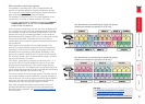
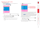
OPTIONS
1
20 12
419 11 318 10 217 9 1
3
2
24 16 823 15 7
22 14 6
21
13
5
4
5V5V
WARNING
!
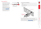
RJ45CONNECTORSONTHIS
PANELAREFORCONNECTION
TOADDERKVMEQUIPMENT
ONLY.
DONOTCONNECTTONETWORKOR
TELEPHONESYSTEMS
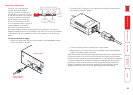
4A4A
AUXPWRINMAINPWRIN
ON
21 43
POWERCONTROL COM1/UPGRADE
COM2/MODEM
KM
USERPORT1
CATxUSERPORTS COMPUTERCONNECTIONS COMPUTERCONNECTIONS COMPUTERCONNECTIONS
Madein
theU.K.
Indooruseonly
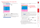
OPTIONS
1
20 12 419 11 318 10 217 9 1
3
2
24 16 823 15 7
22 14 6
21
13
5
4
5V5V
WARNING
!
RJ45CONNECTORSONTHIS
PANELAREFORCONNECTION
TOADDERKVMEQUIPMENT
ONLY.
DONOTCONNECTTONETWORKOR
TELEPHONESYSTEMS
4A4A
AUXPWRINMAINPWRIN
ON
21 43
POWERCONTROL COM1/UPGRADE
COM2/MODEM
KM
USERPORT1
CATxUSERPORTS COMPUTERCONNECTIONS COMPUTERCONNECTIONS COMPUTERCONNECTIONS
Made
in
theU.K.
Indooruseonly
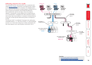
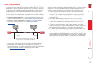
U SU S
CAM CAMCAM CAM
Slave MC5
Master MC5
Master monitorSlave monitor
Computers tted
with dual video
heads
Serial
synchronisation
cable
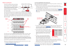
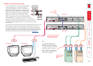
Multiple video head connections
Two or more MC5 units can be connected together
so that they operate in a synchronised manner.
Synchronised operation is useful for applications
that require multiple video signals to be switched
together. This type of operation is usually required
where each computer is tted with multiple video
cards or video cards with multiple video heads.
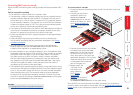
Whenever an MC5 channel is switched, it sends an
RS232 command out on its serial interface (marked
COM1/UPGRADE on the rear panel). An MC5 will switch its
channel if it receives the same command on its serial interface.
Consequently, by linking the serial interfaces, a master unit may
be made to automatically switch one or more slave units as shown
in the diagram.
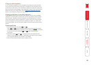
It should be noted that the synchronisation cable deliberately does not have
the transmit pin of the Slave End connector linked to the receive pin of
the Master End connector. To do so would cause the Slave unit to be able
to switch the Master unit. This would setup an endless cyclical switching
sequence that would prevent the MC5 devices from operating correctly. For
more details about the serial synchronisation cables, see Appendix 7.
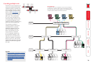
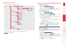
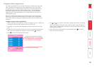
REMOTE
USER
U
S
HOST
COMPUTER
CAM CAM
REMOTE
USER
U S
The local user ports can also
be used to view multiple
video head installations.
Notes
It is recommended that the
second CAM in each pair is a
USB-type and that it is plugged
to a vacant USB port on the host
computer to derive its power.
Pairs of CAMs can be strapped
back-to-back with cable ties to
create a tidy installation.