


41
External Control
Application
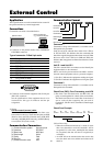
These specifications cover the communications control of
the plasma monitor by external equipment.
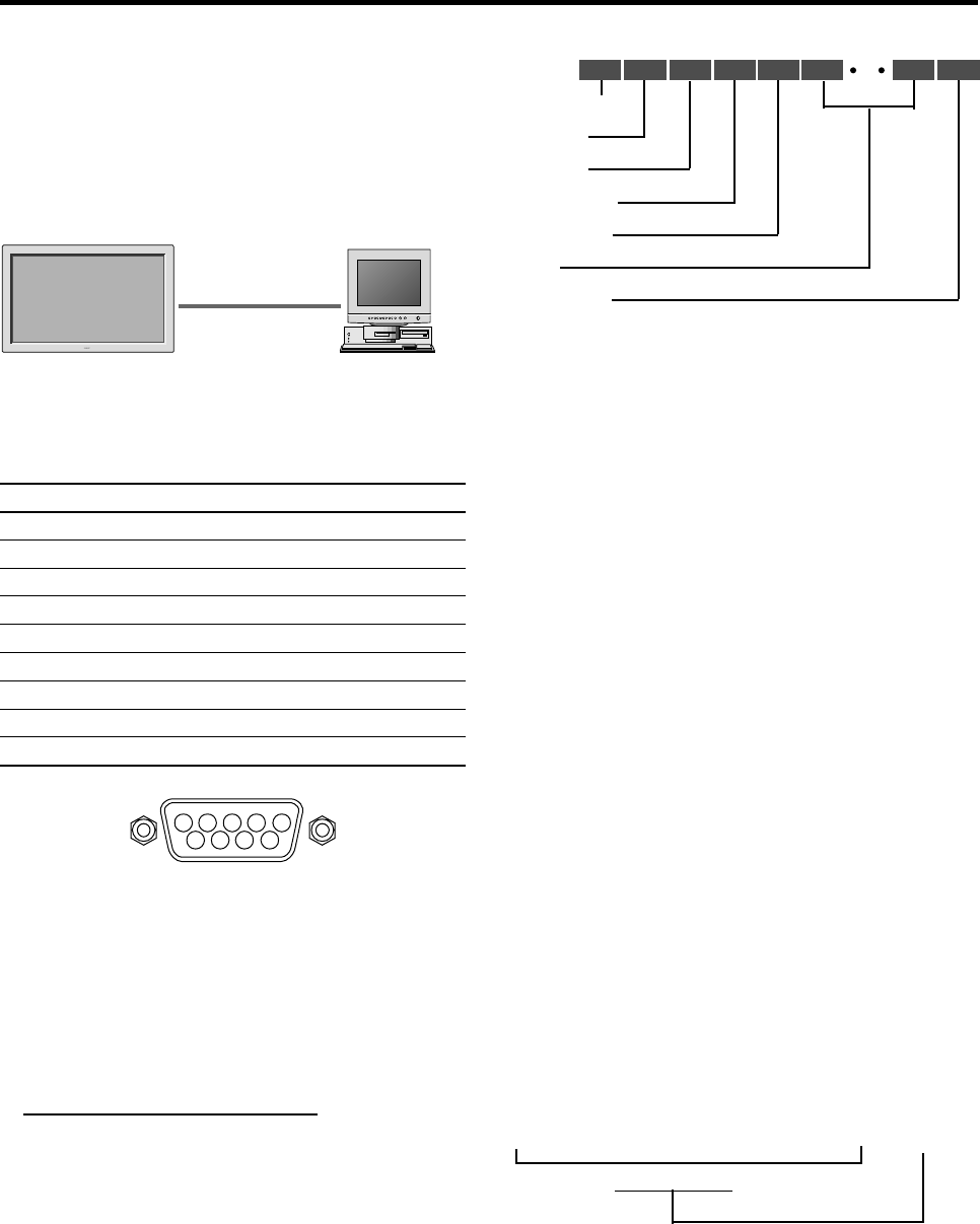
Connections
Connections are made as described below.
plasma monitor
External equipment
e.g., Personal computer
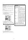
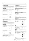
1) Connector on the plasma monitor side: EXTERNAL
CONTROL connector.
Type of connector: D-Sub 9-pin male
No. Pin Name
1 No Connection
2 RXD (Receive data)
3 TXD (Transmit data)
4 DTR (DTE side ready)
5 GND
6 DSR (DCE side ready)
7 RTS (Ready to send)
8 CTS (Clear to send)
9 No Connection
1
5
9
6
2
34
7
8
2) Connector on the external equipment side: Serial port
(RS-232C) connector.
See the specifications of the equipment that is to be
connected for the type of connector and the pin
assignment.
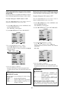
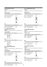
3) Wiring
Use a crossed (reverse) cable.
Wire the cable so that each pair of data lines cross
between the two devices. These data line pairs are RXD
(Receive data) and TXD (Transmit data), DTR (DTE
side ready) and DSR (DCE side ready), and RTS (Ready
to send) and CTS (Clear to send).
Communication Parameters
(1) Communication system Asynchronous
(2) Interface RS-232C
(3) Baud rate 9600 bps
(4) Data length 8 bits
(5) Parity Odd
(6) Stop bit 1 bit
(7) Communication code Hex
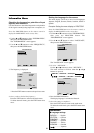
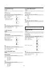
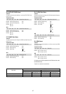
Communication Format
Command 1
Command 1, along with command 2, is a number used to
distinguish each command.
In the case of ACK, when the lower order 4 bits is FH (as
in 3FH and 7FH), this indicates that the commands and
data of the supported equipment have been received. When
the lower order 4 bits is BH (as in 3BH and 7BH), this
indicates that unsupported commands and data have been
received.
Unit ID 1 and Unit ID 2
Unit ID 1 and unit ID 2 are numbers used to identify the
equipment that is to be connected.
60H is used for the plasma monitor and 80H is used for
external control equipment such as a personal computer.
1) Unit ID 1: Indicates the equipment sending the signal
2) Unit ID 2: Indicates the equipment receiving the signal
Command 2
Command 2, along with command 1, is a number used to
distinguish each command.
Check Sum (CKS), Error Processing, and ACK
1) The check sum described below and RS-232C odd
parity are used together for a check of the received data.
The check sum is the lower order 8 bits of one frame of
sent or received data comprising the sum total of
Command 1, Unit ID 1 and 2, Command 2, Data Length,
and Data.
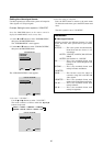
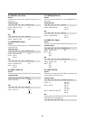
Check Sum Example
2) Error Processing
• When the communication interval is vacant for more
than 4 ms, thereafter a received Command 1 will be
recognized. If, at this time, meaningful data cannot
be recognized, that data will not be recognized (as
valid data).
• An ACK will not be returned unless the receive data
error, the check sum error, and the receive data are all
taken in.
Command 1
Unit ID 1
Unit ID 2
Command 2
Data length
Data
Check sum
8 bit
8 bit 8 bit 8 bit 8 bit 8 bit 8 bit 8 bit
DFH 80H 60H 47H 01H 01H 08H
Command 1 Unit ID 1 Unit ID 2 Command 2 Data Length Data Check Sum
Total 208H
▲