


35
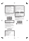
Application
These specifications cover the communications control of
the plasma monitor by external equipment.
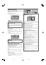
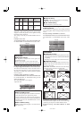
Connections
Connections are made as described below.
Connector on the plasma monitor side: EXTERNAL
CONTROL connector.
Use a crossed (reverse) cable.
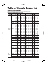
Type of connector: D-Sub 9-pin male
1
5
9
6
2
34
7
8
Communication Parameters
(1) Communication system Asynchronous
(2) Interface RS-232C
(3) Baud rate 9600 bps
(4) Data length 8 bits
(5) Parity Odd
(6) Stop bit 1 bit
(7) Communication code Hex
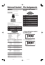
External Control Codes (Reference)
FUNCTION CODE DATA
Power ON 9FH 80H 60H 4EH 00H CDH
OFF 9FH 80H 60H 4FH 00H CEH
Input Switch Video1 (RCA) DFH 80H 60H 47H 01H 01H 08H
Video2 (S-Video) DFH 80H 60H 47H 01H 02H 09H
DVD/HD1 (RCA) DFH 80H 60H 47H 01H 05H 0CH
DVD/HD2 (RCA) DFH 80H 60H 47H 01H 06H 0DH
DVD/HD3 (HDMI) DFH 80H 60H 47H 01H 0EH 15H
PC/RGB (mini D-sub 15-pin) DFH 80H 60H 47H 01H 07H 0EH
DVD/HD4 (HDMI) DFH 80H 60H 47H 01H 1AH 21H
Audio Mute ON 9FH 80H 60H 3EH 00H BDH
OFF 9FH 80H 60H 3FH 00H BEH
Picture Mode NORMAL DFH 80H 60H OAH 01H 01H CBH
THEATER 1 DFH 80H 60H OAH 01H 02H CCH
THEATER 2 DFH 80H 60H OAH 01H 03H CDH
DEFAULT DFH 80H 60H OAH 01H 04H CEH
BRIGHT DFH 80H 60H OAH 01H 05H CFH
Screen Mode STADIUM DFH 80H 60H 51H 01H 02H 13H
ZOOM DFH 80H 60H 51H 01H 03H 14H
NORMAL DFH 80H 60H 51H 01H 04H 15H
ANAMORPHIC DFH 80H 60H 51H 01H 05H 16H
UNDERSCAN DFH 80H 60H 51H 01H 08H 19H
14 : 9 DFH 80H 60H 51H 01H 09H 1AH
2.35 : 1 DFH 80H 60H 51H 01H 0AH 1BH
Auto Picture ON DFH 80H 60H 7FH 03H 03H 09H 00H 4DH
OFF DFH 80H 60H 7FH 03H 03H 09H 01H 4EH
Cinema Mode ON DFH 80H 60H C1H 01H 01H 82H
OFF DFH 80H 60H C1H 01H 02H 83H
Note:
Contact your local dealer for a full list of the
External Control Codes if needed.
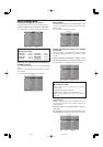
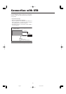
Display
External equipment
e.g., Personal computer
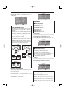
Pin Name
No Connection
RXD (Receive data)
TXD (Transmit data)
DTR (DTE side ready)
GND
Pin No.
1
2
3
4
5
Pin No.
6
7
8
9
Pin Name
DSR (DCE side ready)
RTS (Ready to send)
CTS (Clear to send)
No connection
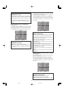
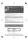
5 4 3 2 1
15 14 13 12 11
10 9 8 7 6
PC/RGB
mini D-Sub 15-pin connector
(Analog)
Signal (Analog)
Red
Green or sync-on-green
Blue
No connection
Ground
Red ground
Green ground
Blue ground
No connection
Sync signal ground
No connection
Bi-directional DATA (SDA)
Horizontal sync or Composite sync
Vertical sync
Data clock
Pin No.
1
2
3
4
5
6
7
8
9
10
11
12
13
14
15
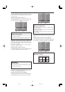
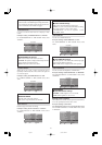
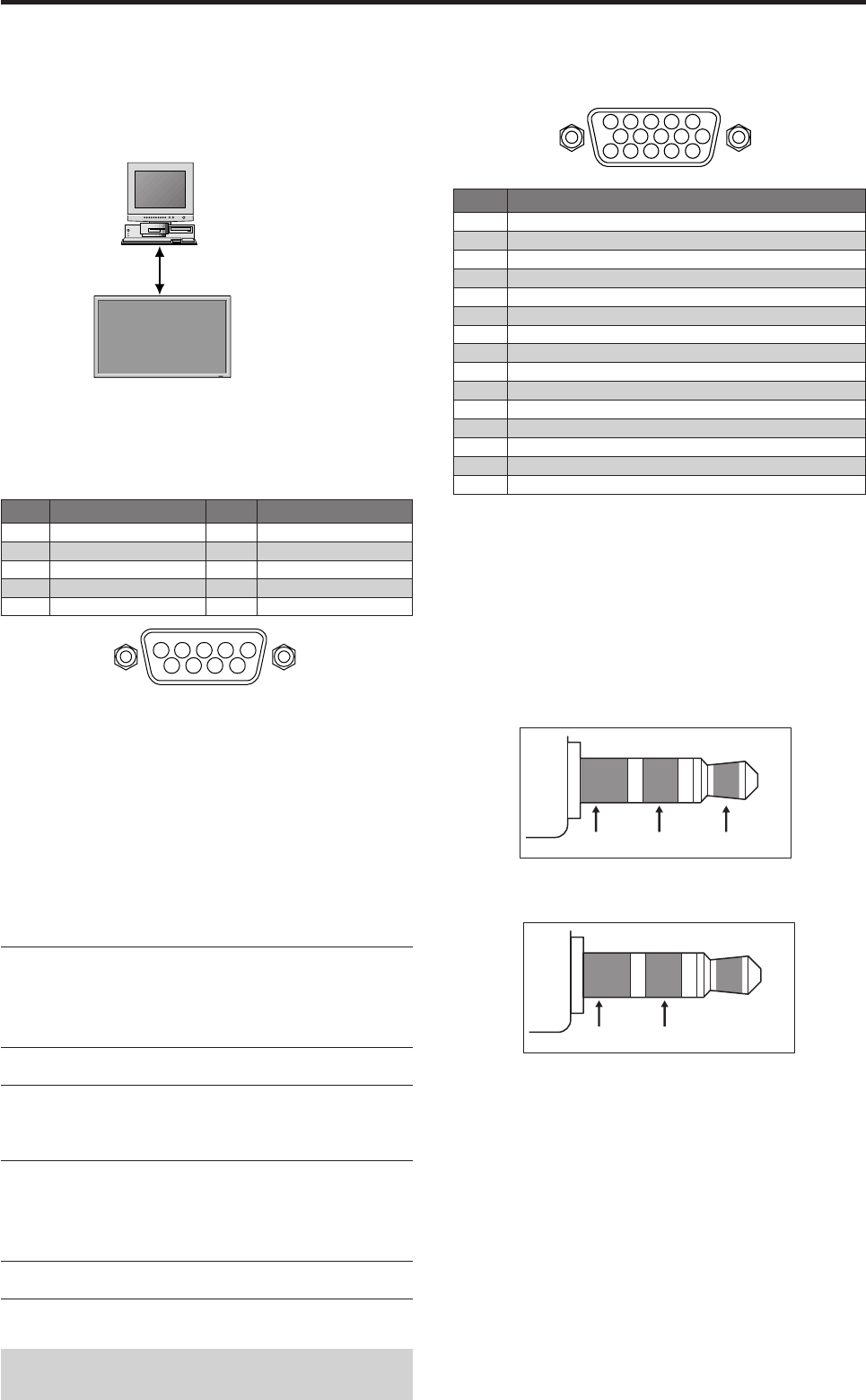
External Control Pin Assignments
1/8 Stereo Mini Jack (not supplied)
for REMOTE IN/OUT
Plasma monitor REMOTE IN
Plasma monitor REMOTE OUT
GND VDD (DC +3 V)DATA (DC +5 V)
GND DATA (C-MOS DC +5 V)
06.9.7, 4:28 PMPage 35