7
T
O
BUILD
THE
SERIAL
LINK
1. Use shielded twisted-pair cable.
A reliable data connection begins
with the right cable. Microphone cable cannot transmit DMX data reliably
over long runs. For best results, use only cable designed for RS-485
applications. Your Martin dealer has a range of cables, connectors, and
adaptors designed for lighting control.
2. Starting from the controller, connect output to input.
Check the
pin-out on Martin fixtures and be sure to connect hot to hot and cold
to cold.
3. Never use a “Y” connector to split the link.
If you need to split
the serial link into branches use a dedicated splitter/amplifier such
as the Martin 4-Channel Opto-Isolated RS-485 Splitter.
4. Don’t overload the link.
Placing more than 32 devices on a link
can cause unpredictable performance. The control units for the
RoboColor IIx and RoboColor III systems, the Martin DMX Switch
Pack, and the Martin DMX Interface each count as 1 device.
5. Always terminate the link
by installing the provided termination
plug in the output socket of the last fixture on the link. The termina-
tion plug, which is a male XLR connector with a 120 ohm resistor
soldered between pins 2 and 3, “soaks up” the control signal so it
cannot reflect back down the link. If a splitter is used, terminate
each branch of the link.
C
ONNECTING
THE
POWER
SUPPLY
For safe operation, the controller must be
grounded (earthed).
T
O
INSTALL
A
PLUG
The 2518 DMX Controller is delivered without a plug on the power cord. Following
the manufacturer’s instructions, install an approved 3-prong grounding-type plug that
fits your supply. Connect the wires to the pins as listed below. If the pins are not
clearly identified, or if you have any doubts about proper installation, consult a qual-
ified electrician.
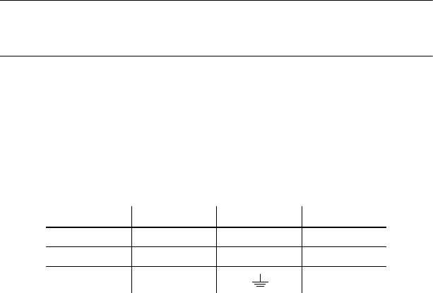
Wire Pin Marking Screw color
brown live “L” yellow or brass
blue neutral “N” silver
yellow/green ground green
Table 3: Plug Wiring


