


9-6
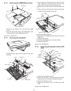
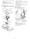
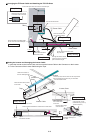
1. Disconnect the LCD/INV. Cable from the Connector on
the Inverter.
2. Remove the LCD Unit.
3. Remove the Inverter with the Inverter Case.
4. Remove the two Screws <N18>, and then the W-LAN
PCB L and R.
Screws <N18>: XQN17+BJ6FJ
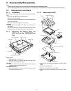
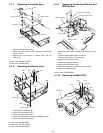
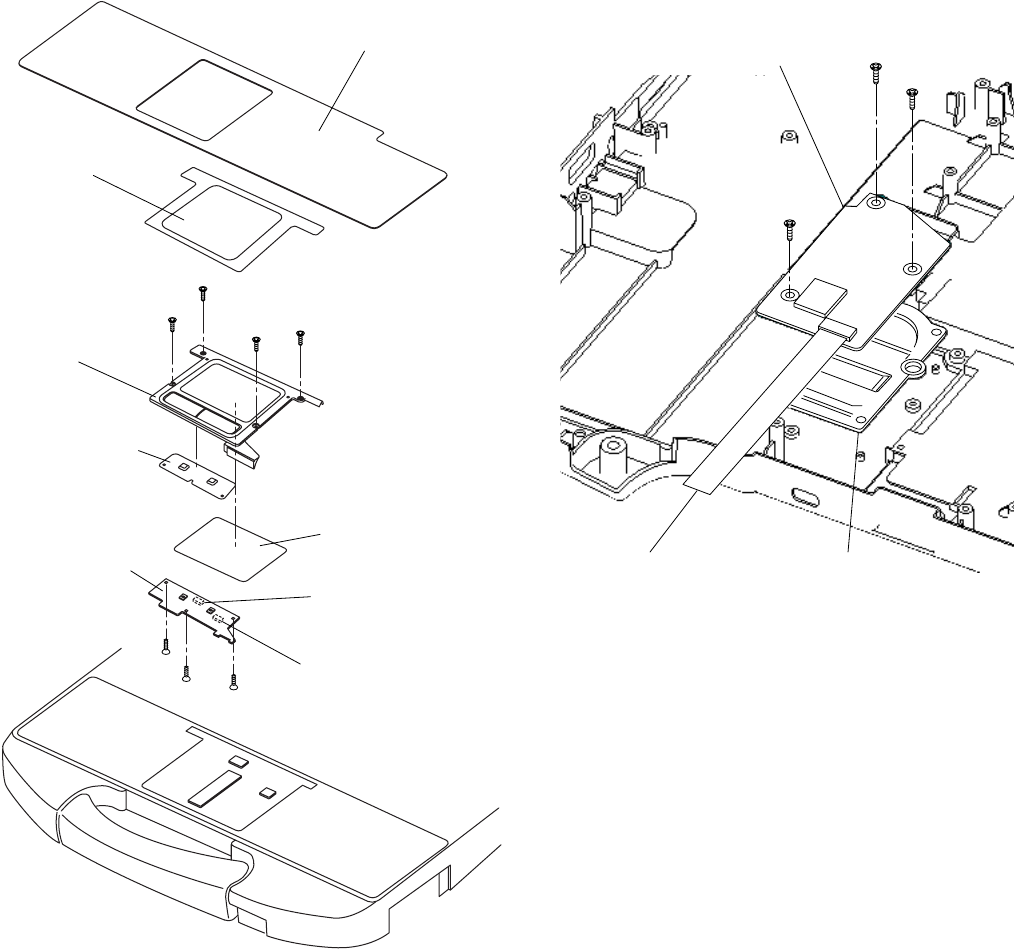
9.1.18. Removing the Touch PAD and PAD
PCB
1. Remove the Palm Rest Sheet.
2. Remove the four Screws <N20>, and then PAD Base
Ass'y.
3. Disconnect the two Cables from the two Connectors
(CN1301, CN1302).
4. Remove the three Screws <N14>.
5. Remove the PAD Button WP Rubber and PAD SW PCB.
6. Remove the Touch PAD.
Screws <N14>: DRHM0106ZA
Screws <N20>: DXQT2+G4FCL
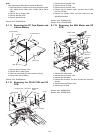
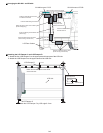
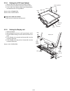
9.1.19. Removing the Finger PCB
Preparation
Perform the steps up to removing of the Main PCB.
1. Remove the three Screws. <N9>
2. Remove the Finger PCB and Finger Sensor Base.
Screws <N9>: DFHE5025XA
Palm Rest Sheet
Pad WP Sheet A
PAD Base Ass’y
PAD Button
WP Rubber
Touch PAD
PAD SW PCB
<N20>
<N20>
<N20>
<N20>
CN1302
CN1301
<N14>
<N14>
<N14>
<N9>
Finger PCB
Finger Sensor Base
FP FFC Cable
<N9>
<N9>