


9-17
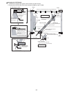
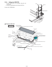
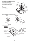
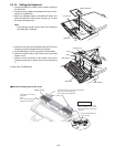
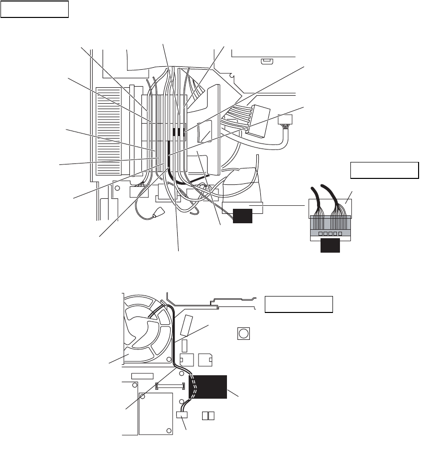
Q Arranging the Cables to the Cable Holder and their Wiring Order
• Pull the surplus length of the Cable coming from the LCD side to inside of the unit.
(If the surplus length comes outside, it will be caught by the center cover during setting.)
• Fit the Cables to the corresponding grooves of the Cable Holder.
• Ensure the Cables in the Cable Holder are wired in the correct order.
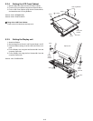
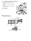
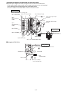
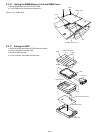
Q Arranging the FAN Cable
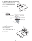
No.1: LAN Cable
No.2:
Black Antenna
Cable
No.3:
Gray Antenna
Cable
No.4: Empty
No.5: I/O Cable
No.6: LCD Cable
No.7: LCD Cable with the tube
No.8: TP Power Cable
No.9: Modem Cable
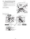
Cable Holder
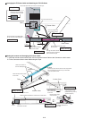
Cover the Cables
using the Tape.
Fold the Tape in half
and attach it to the Cables.
Safety Working
Fit the portion using the Tape
in the notch.
Fit the Black Tube to the end
of the rib.
Be sure to wire the Cables in the correct order.
Safety Working
FAN Motor
Tape
Main PCB
Connector (CN28)
FAN Cable
Lead the FAN Cable into the space next to the Board.
Fix the FAN Cable.
Connect the FAN Cable.
Safety Working