


10
OPERA
TION
SET-UP FEATURES
The MB Quart R Series amplifier offers a wide range of selections for the user to create a listening
environment that meets your personal preference.
Before making final adjustments, read through the descriptions for each feature to get the best results.
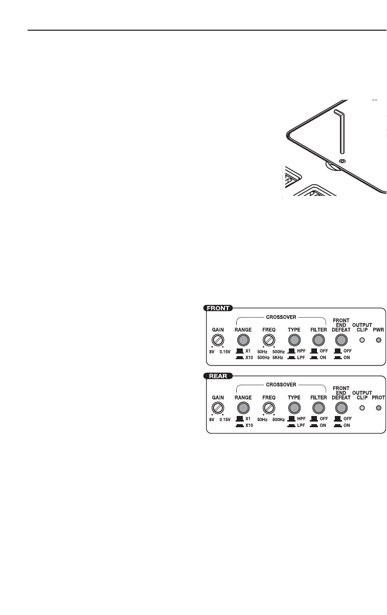
ADJUSTMENTS
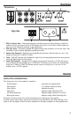
Loosen the allen screw holding the small cover in place over the controls. Tilt
the cover up and away from the amplifier. After making adjustments, always
ensure the cover is in place to prevent accidental changes to the settings.
NOTE: Failure to follow these instructions may result in a loss of sonic
quality. This is caused by premature activation of the protection
circuitry to maintain the integrity of the amplifiers sensitive
components. The performance specifications listed in this manual
cannot be guaranteed under such conditions.
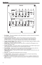
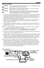
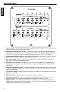
FRONT END DEFEAT
The front-end defeat switch is responsible for rerouting the signal around the
signal processing circuitry within the amplifier. This feature was designed for use with external processors to
provide the purest possible signal path through the amplifier.
With this configuration, the MB Quart R Series amplifiers are able to provide lower distortion and better
signal reproduction due to the reduction in the number of components in the signal path. Bypassing the
crossover will also eliminate the typical phase shift associated with the analog filter transform function. While
the Front End Bypass is turned on, all adjustments made to the gain or crossover will be bypassed.
CROSSOVER
Do the following individually for each channel.
Filter Switch
Placing the switch in the ON position (In Position)
sets the amplifier to the All Pass mode, preventing
any crossover adjustment, allowing all frequencies
to pass. Adjustments made to the Multiplier switch
or Frequency Adjuster are bypassed.
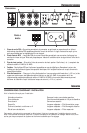
Frequency Switch
Placing the switch in the HPF position (In Position)
sets the amplifier to the High Pass mode, enabling
frequencies above the cut-off point to pass.
Placing the switch in the LPF position (Out Position)
sets the amplifier to the Low Pass mode, enabling
frequencies below the cut-off point to pass.
Multiplier Switch
This switch sets the multiplier for the crossover frequencies.
Placing the switch in the x10 position (In Position) sets the adjustable crossover frequency to 500-5KHz
(5000Hz).
Placing the switch in the x1 position (Out Position) sets the adjustable crossover frequency to 50-500Hz.
Frequency Adjustment
After setting the Frequency Switch and Multiplier Switch, use the Frequency Adjuster to set the desired cut-
off point.
Turning the adjuster counter-clockwise decreases the set frequency.
Turning the adjuster clockwise increases the set frequency.
Quick Setting: Decrease the crossover frequency all the way down. With the system playing, increase the crossover
frequency up slowly until the desired crossover point is achieved.