


5
DESIGN FEA
TURES
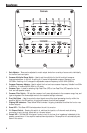
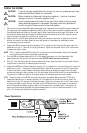
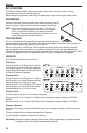
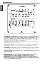
1. RCA Line Output Jacks – These outputs provide a convenient source for daisy-chaining an additional
amplifier without running an extra set of RCA cables from the front of the vehicle. These are pass-thru
only and are not effected by crossover or gain adjustments.
2. RCA Input Jacks – The industry standard RCA jacks provide an easy connection for line level input. They
are plated to resist the signal degradation caused by corrosion.
3. Speaker Plug Receptacle – Receptacle for the speaker plug connector. These connectors (+ and –) will
accept wire sizes from 12 AWG to 18 AWG.
4. Fuses – These ATC fuses are easily accessible in case of failure. Always replace fuses with same type and
rating. See Specifications for fuse ratings.
5. Power Plug Receptacle – Receptacle for the power plug connector. The power (+12V DC) and ground
wire connectors will accommodate up to a 2 AWG wire. The Remote wire connector will accommodate
sizes from 12 AWG to 18 AWG. The Remote terminal is used to remotely turn-on and turn-off the
amplifier when +12V DC is applied.
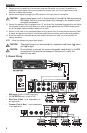
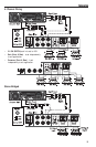
Connections
Left Side
Right Side
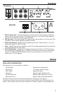
INSTALLATION CONSIDERATIONS
The following is a list of tools needed for installation:
Volt/Ohm Meter
Wire strippers
Wire crimpers
Wire cutters
#2 Phillips screwdriver
Battery post wrench
Hand held drill w/assorted bits
1/8" diameter heatshrink tubing
Assorted connectors
Adequate Length—Red Power Wire
Adequate Length—Remote Turn-on Wire
Adequate Length—Black Grounding Wire
This section focuses on some of the vehicle considerations for installing your new amplifier.
Pre-planning your system layout and best wiring routes will save installation time. When deciding on the
layout of your new system, be sure that each component will be easily accessible for making adjustments.
INSTALL
ATION