


7
INST
ALLATION
WIRING THE SYSTEM
CAUTION: If you do not feel comfortable with wiring your new unit, please see your local
authorized MB Quart Dealer for installation.
CAUTION: Before installation, disconnect the battery negative (-) terminal to prevent
damage to the unit, fire and/or possible injury.
CAUTION: Avoid running power wires near the low level input cables, antenna, power
leads, sensitive equipment or harnesses. The power wires carry substantial
current and could induce noise into the audio system.
1. Plan the wire routing. Keep RCA cables close together but isolated from the amplifier's power cables and
any high power auto accessories, especially electric motors. This is done to prevent coupling the noise
from radiated electrical fields into the audio signal. When feeding the wires through the firewall or any
metal barrier, protect them with plastic or rubber grommets to prevent short circuits. Leave the wires
long at this point to adjust for a precise fit at a later time.
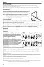
2. Remove the four (4) 8/32 allen head screws holding the connection end cover in place (this is the end
without the vents for the fans). Keep the cover and screws in a safe place for reinstallation when
mounting and wiring is complete.
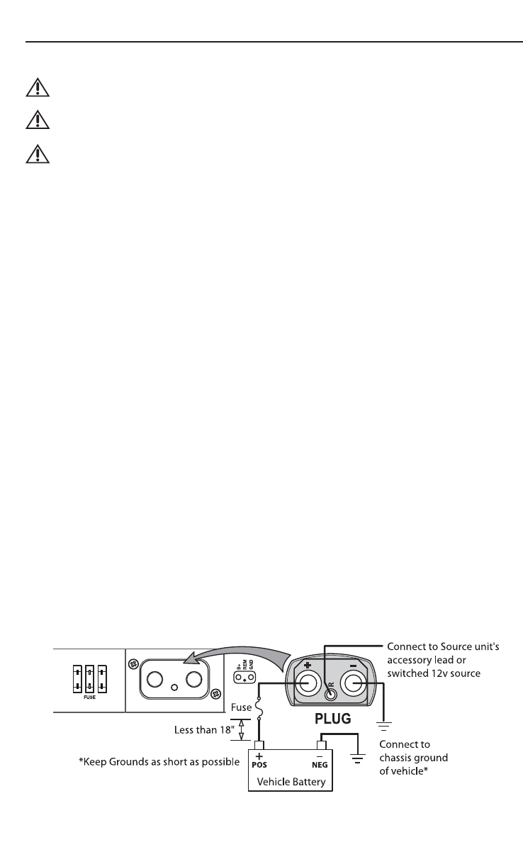
3. Prepare the RED wire (power cable) by stripping 1/2" of insulation from the end of the wire. Insert the
bared wire into the “+” terminal on the plug connector. Tighten the set screw with a 3/32" allen wrench
to secure the cable in place.
NOTE: The "+" (positive) cable MUST be fused 18" or less from the vehicle's battery. Install the fuseholder
under the hood and ensure connections are water tight.
4. Trim the RED wire (power cable) within 18" of the battery and splice in a inline fuse holder. See
Specifications for the rating of the fuse to be used. DO NOT install the fuse at this time.
5. Strip 1/2" from the battery end of the power cable and crimp a large ring terminal to the cable. Use the
ring terminal to connect to the battery positive terminal.
6. Prepare the BLACK wire (Ground cable) by stripping 1/2" of insulation from the end of the wire. Insert the
bared wire into the “-” terminal on the plug connector. Tighten the set screw with a 3/32" allen wrench
to secure the cable in place. Prepare the vehicle chassis ground by scraping any paint from the metal
surface and thoroughly clean the area of all dirt and grease. Strip the other end of the wire and attach a
ring connector. Fasten the cable to the chassis using a non-anodized screw and a star washer.
NOTE: Keep the length of the BLACK wire (Ground) as short as possible. Always less than 30"(76.2cm).
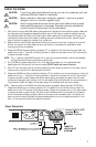
7. Prepare the Remote turn-on wire by stripping 1/2" of insulation from the end of the wire. Insert the
bared wire into the “R” terminal on the plug connector. Tighten the set screw with a 3/16" allen wrench
to secure the cable in place. Connect the other end of the Remote wire to a switched 12 volt positive
source. The switched voltage is usually taken from the source unit's accessory lead. If the source unit
does not have this output available, the recommended solution is to wire a mechanical switch in line
with a 12 volt source to activate the amplifier manually.
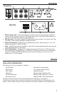
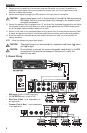
Power Connection