


Pressure Systems, Inc. Model 9116 User’s Manual
Page 114 www.PressureSystems.com
5.1.6.3 Adapter Plate O-Ring Replacement
Following is a step-by-step procedure to replace Adapter plate O-rings in a Model 9116
Intelligent Pressure Scanner. The adapter plate is located opposite of the tubing plate on the
calibration manifold. All DH200 transducers are attached to the adapter plate.
(1) Disassemble the module as described in Section 5.1.2.
(2) Remove the PC-327 Analog board as described in Section 5.1.3.1. Lay the circuit board to
the side on an anti-static surface.
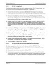
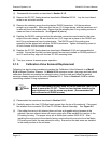
(3) Remove the six (6) 3/32" Allen-head screws that secure the adapter plate to the calibration
valve housing. To remove the two (2) center screws, you must remove the DH200
transducers near the screws. Make sure to note the DH200 serial number and location.
The plate should be gently lifted from the calibration housing.
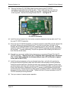
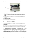
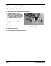
(4) Carefully rotate or slide the adapter plate back and forth, pivoting on the guiding pin about
1/8" several times. This is done to loosen the O-rings from the calibration manifold. Lift the
adapter plate straight up. Do not touch the calibration manifold.
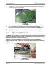
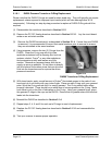
(5) Remove and replace the O-rings needing maintenance using the procedure described in
Section 5.1.6.1. Note that the O-ring seals use an additional Teflon cup seal placed on top
of the O-ring. These Teflon seals do not require Krytox
®
grease.
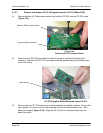
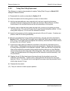
(6) Examine the adapter plate and calibration valve surface to verify that no contaminants are
on either surface. This generally requires microscopic examination. Replace the adapter
plate by slowly placing the plate on the calibration manifold. Make sure that the O-ring is
down towards the pneumatic sliding manifold and the guiding pin on the adapter plate fits
into the mating hole of the calibration valve housing. Fasten the adapter plate evenly on all
sides.
(7) Install the DH200 transducers that were previously removed. It is suggested to install them
back in their original location.
(8) Replace the PC-327 Analog board as described in Section 5.1.3.1 and reassemble the
module.
(9) Test your scanner to ensure proper operation.