


Pressure Systems, Inc. Model 9116 User’s Manual
Page 118 www.PressureSystems.com
Chapter 6
Troubleshooting Guide
6.1 Ethernet Module Troubleshooting
6.1.1 Checking Module Power-Up Sequence
(1) Proper power to the module should first be verified. If possible, verify that the output of
the module power supply is set within the range of 18-36 VDC. This should be nominally
set for 24 VDC. Ensure the power supply setting is high enough to compensate for
cable voltage drops if long interface cable lengths are used.
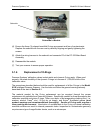
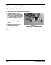
(2) Turn module power switch ON and verify the following top panel LED status following
initial power-up :
• PWR LED should remain ON
If this LED is not on, all other LED’s will likely also be off. Check the PSI 90DB, remote
power supply (8491), or customer provided power supply to ensure the proper voltage
(18-36 VDC) is being provided. Also verify that the power pins in the module interface
cable are wired as described in Section 2.3.2 and Appendix D
• COL LED will illuminate briefly upon power-up. This gives a visual indication that the
LED is functional. Thereafter, the LED should remain OFF.
• Tx LED will illuminate briefly upon power-up. This gives a visual indication that the LED
is functional. Subsequent activity on the Tx LED during the power-up
sequence is indication that the RARP/BOOTP protocol is enabled. This will typically
occur following the initial busy (BSY) LED cycle and continue until an appropriate RARP
reply is received.
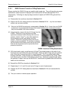
• LNK LED will illuminate briefly upon power-up. This gives a visual indication that the
LED is functional. Thereafter, the LED will indicate proper connection to an Ethernet
hub or switch, and should remain ON.
If this LED is OFF, verify that the module is properly connected to the
communications hub or switch. Verify proper power is applied to the hub. Also
try connecting the 9116 cable to a different port of the hub. Note that most hubs
have similar link LEDs to indicate proper connection to the hub itself. If present,
verify that the hub link LED for the pressure scanner and the host computer are
both active. If the hub is functioning correctly, verify that the communications
pins in the module interface cable are wired as described in Section 2.3.4.1 and
Appendix D.