


Pressure Systems, Inc. Model 9116 User’s Manual
Page 13 www.PressureSystems.com
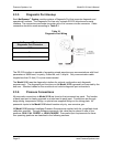
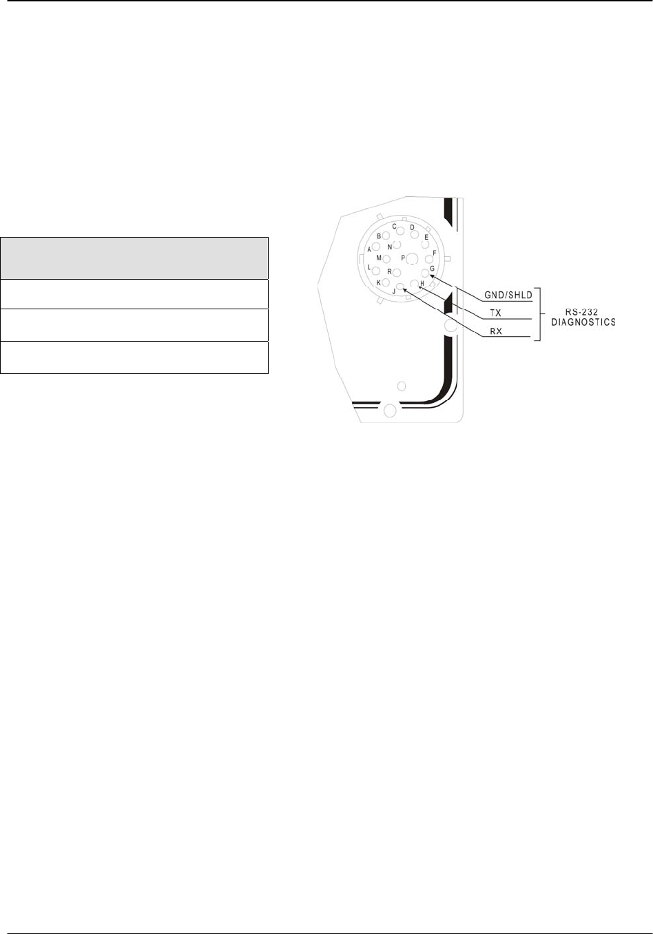
2.3.5 Diagnostic Port Hookup
Each NetScanner
™
System module contains a Diagnostic Port that supports diagnostic and
operational functions. The Diagnostic Port has only a simple RS-232 asynchronous serial
interface. The connections are made via certain pins of its common circular connector. Cable
connection should be made according to Table 2.1.
Table 2.1
Diagnostic Port Wiring
NetScanner
™
System
Diagnostic Port Connector
GND
Tx
Rx
The RS-232 interface is capable of supporting simple asynchronous communications with fixed
parameters of 9600 baud, no parity, 8 data bits, and 1 stop bit. Only communication cable
lengths less than 30 feet (10 m) are recommended.
The Model 9116 uses the diagnostic interface for optional configuration and diagnostic
purposes only. The diagnostic port functions on the Model 9116 is generally not required by the
end user. Standard cables for this module do not include diagnostic port connections.
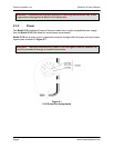
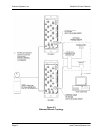
2.3.6 Pressure Connections
All pneumatic connections to Model 9116 are found on the instrument top panel. The function
of each input port is clearly engraved or printed next to each input. Connections are through
bulge tubing, compression fittings, or special user-supplied fittings on the tubing plate. All
pneumatic inputs to the Model 9116 should contain only dry, non-corrosive gas.
All Model 9116 standard Intelligent Pressure Scanners are supplied with the purge/leak check
calibration manifold. Through software commands, this valve may be placed in one of four
positions; RUN, CAL, PURGE, or LEAK-CHARGE. Pneumatic input requirements for these
four operating positions are described in the following sections.