


9
8
7
6
5
3
4
2
1
6
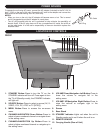
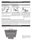
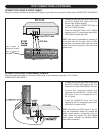
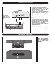
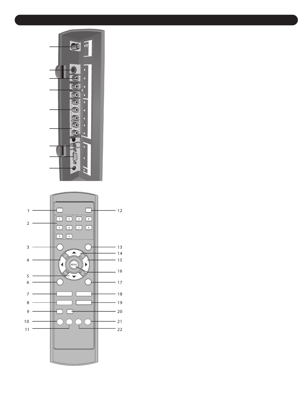
LOCATION OF CONTROLS (CONTINUED)
The side panel is accessible by pressing in on the side
c
over tabs, then lifting the side cover. After connections
have been made, slide the wires through the bottom
opening of the side cover and replace the side cover.
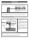
1. UHF/VHF Antenna IN Jack
2. S-VIDEO IN Jack
3. VIDEO IN Jack
4. AUDIO Left/Right IN Jacks (For S-Video or AV input)
5. COMPONENT IN Jacks (Y/P
B/PR)
6. COMPONENT IN Audio Left/Right Jacks
7. VGA (PC) AUDIO IN Jack
8. VGA (PC) IN Jack
9. DC 12V IN Jack (
z
z
)
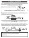
(DETACHABLE POWER CORD PART NO. 023-25040-120*,
AC ADAPTER PART NO. 059-34190-201*)
SIDE PANEL COVER PART NO. 138-31190-040-V*
SIDE
PANEL
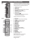
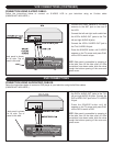
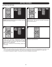
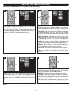
REMOTE
1. MUTE Button
2. Direct Channel Selection/Number (0-9) Buttons
3. -/-- Button
4. VOLUME Down/Navigation Left Button
5. CHANNEL/Navigation Down Button
6. DISPLAY Button
7. SLEEP Button
8. SOUND Button
9.
INFO Button
10.
RETURN Button
1
1.
PROG LIST Button
12.
ST
ANDBY Button
13.
SOURCE Button
14.
CHANNEL/Navigation Up Button
15.
VOLUME UP/Navigation Right Button
16.
MENU Button
17.
PICTURE Button
18.
CCD Button
19.
MTS Button
20.
GUIDE Button
21.
FAVORITE (Channel) Button
22. SOUND LIST Button
REMOTE CONTROL PART NO. HS-Y3719-BLK-320*
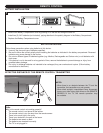
BA
TTER
Y
COVER
P
ART NO. 1
1
1-03530-010*
*Consumer Replaceable Part
(See page 40 to order
.)