


28
IS4910
D
EVICE
D
RIVER
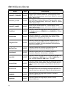
Value Type Description
POLARITY_TRIGGER
DWORD
(Optional) Defines the polarity (active “high” or “low”) of the
“Trigger” signal. Allowed values are 1 (normal polarity, active
“high”) and 0 (inverted polarity, active “low”). Default is 1 (normal
polarity, active “high”).
POLARITY_ILLUM
DWORD
(Optional) Defines the polarity (active “high” or “low”) of the
“Illum_ON” signal. Allowed values are 1 (normal polarity, active
“high”) and 0 (inverted polarity, active “low”). Default is 1 (normal
polarity, active “high”).
POLARITY_AIMER
DWORD
(Optional) Defines the polarity (active “high” or “low”) of the
“Aimer” signal. Allowed values are 1 (normal polarity, active
“high”) and 0 (inverted polarity, active “low”). Default is 1 (normal
polarity, active “high”).
PixelClock
DWORD
(Optional) Defines the image sensor pixel clock frequency, in
Hz. Allowed values are 12000000 Hz and 24000000 Hz. Default
is 24000000 Hz.
I2CBusClock
DWORD
(Optional) Defines the I
2
C bus transfer rate, in Hz. Allowed
values are 100000 Hz (standard mode) and 400000 Hz (fast
mode). Default is 400000 Hz (fast mode).
IntegrationTime
DWORD
(Optional) Defines the image integration (exposure) time, in
microseconds. Default is 8000 µs. In the snapshot mode, if
illumination is enabled, the image integration time equals the
maximum illumination time.
MinFlashTime
DWORD
(Optional) Defines the minimum illumination time for the
snapshot mode, in microseconds. Default is 0 µs.
IllumControl
DWORD
(Optional) Enables (value of 1) or disables (value of 0)
illumination. Default is 1 (illumination is enabled).
Gain1000
DWORD
(Optional) Defines the image sensor absolute gain multiplied by
1000. It ranges from 1000 (Gain = 1 or 0 dB) to 16000 (Gain =
16 or 24.08 dB). Default is 1000 (Gain = 1 or 0 dB).
ReverseRows
DWORD
(Optional) Defines order in which rows are transferred from the
image sensor: 0 is normal readout (from top to bottom) and 1 is
reversed readout (from bottom to top). Default is 0 (reversed
order).
ReverseCols
DWORD
(Optional) Defines order in which columns are transferred from
the image sensor: 0 is normal order (from left to right) and 1 is
reversed order (from right to left). Default is 0 (reversed order).
ImgWidth
DWORD
(Optional) Defines the image width (number of columns).
Default is 1280 columns.
ImgHeight
DWORD
(Optional) Defines the image height (number of rows).
Default is 960 rows.