32
A
PPENDIX
B:
IS4910
D
RIVER
I
NITIALIZATION
F
ILE
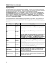
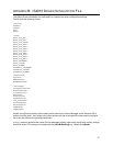
Index (optional) defines the instance number of the device and can be a single decimal digit starting
from 1 (first instance) to 9 (ninth instance) and 0 (tenth instance). The Index number is appended to the
VUQ prefix to construct the device name. Default is 1.
DLL specifies the name of the DLL that implements the driver (vuqdrv.dll).
Path specifies the full path to the DLL that implements the driver.
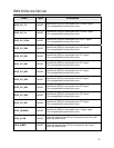
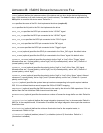
GPIO_CIF_FV specifies the GPIO pin connected to the “VSYNC” signal.
GPIO_CIF_LV specifies the GPIO pin connected to the “HSYNC” signal.
GPIO_CIF_PCLK specifies the GPIO pin connected to the “PCLK” signal.
GPIO_CIF_DD# specifies the GPIO pin connected to the “D#” signal
GPIO_TRIGGER specifies the GPIO pin connected to the “Trigger” signal.
GPIO_ILLUM (optional) specifies the GPIO pin connected to the “Illum_ON” signal. No default value.
GPIO_AIMER (optional) specifies the GPIO pin connected to the “Aimer” signal. No default value.
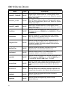
POLARITY_TRIGGER (optional) specifies the polarity (active “high” or “low”) of the “Trigger” signal.
Allowed values are 1 (normal polarity, active “high”) and 0 (inverted polarity, active “low”). Default is 1
(normal polarity, active “high”).
POLARITY_ILLUM (optional) specifies the polarity (active “high” or “low”) of the “Illum_ON” signal.
Allowed values are 1 (normal polarity, active “high”) and 0 (inverted polarity, active “low”). Default is 1
(normal polarity, active “high”).
POLARITY_AIMER (optional) specifies the polarity (active “high” or “low”) of the “Aimer” signal. Allowed
values are 1 (normal polarity, active “high”) and 0 (inverted polarity, active “low”). Default is 1 (normal
polarity, active “high”).
SysIntr (optional) specifies the system interrupt number corresponding to the quick capture interface
IRQ. If it’s not defined the driver would request the IRQ-to-SYSINTR mapping.
DMAChannel (optional) specifies the DMA channel to be used by the driver for DMA operations. If it’s not
defined then the first found free DMA channel would be used.
MaxMemFrames (optional) specifies the maximum number of frames the image buffer can hold. Default is
4.
IntegrationTime (optional) defines the image integration (exposure) time, in microseconds. Default is
8000 µs. In the snapshot mode, if illumination is enabled, the image integration time equals the maximum
illumination time.
MinFlashTime (optional) defines the minimum illumination time for the snapshot mode, in
microseconds. Default is 0 µs.
IllumControl (optional) enables (value of 1) or disables (value of 0) illumination. Default is 1
(illumination is enabled).


