


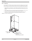
Optional Steps
Should you require AC power on site prior to the arrival of the MGE Field Engineer, the following procedure will
provide the AC power in the bypass mode. Should you have any questions about this procedure, do not hesitate
to contact MGE Customer Support.
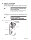
A. Ensure that all switches, CB1-5 in the STS are open (off).
B. Apply input power to the source S1 input of the STS by closing the upstream circuit breaker for source S1. The
STS controls will power up and issues alarm(s). Silence the alarm buzzer by pressing the “Alarm Silence”
pushbutton on the front display panel.
C. Lock CB5 (S2 bypass switch) and remove the lock key (for 4-interlock system, also lock CB2 and remove key).
Using key(s), unlock and close CB4 (S1 bypass switch).
D.
At this point, power will be available for site usage until the STS is properly
commissioned.
E. Upon arrival of the MGE Field Service Engineer, the main power must be disconnected so that a safe and
proper commissioning of the unit may be accomplished.
WARNING Do not, under any circumstance, close CB1, CB2, CB3A and
CB3B (if installed) until the unit has been commissioned by an
MGE Field Engineer.
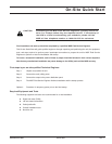
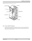
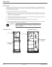
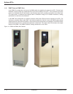
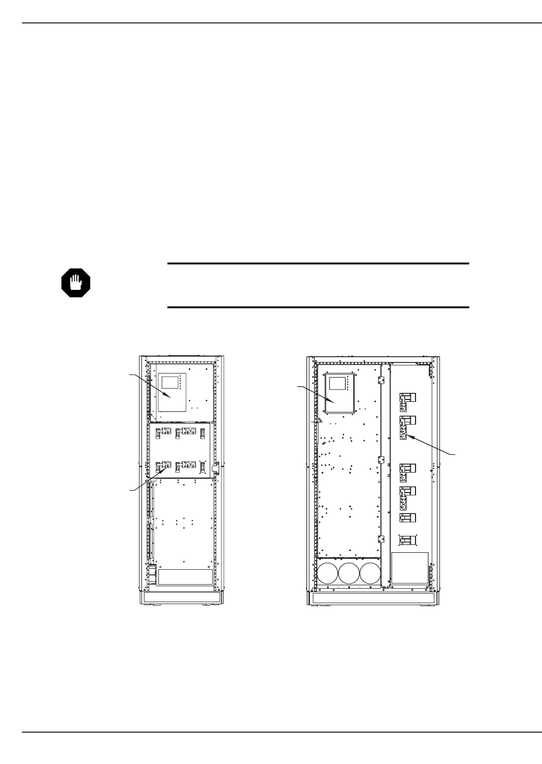
Figure QS-5a 200A STS Figure QS-5b 400/600A STS
Epilson STS
TM
Quick startQS —6 86-504004-00 B03
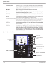
KEY INTERLOCKS
(2 - STANDARD
4 - OPTIONAL)
STS MONITOR
CB1
CB2
CB4
CB5
CB3A
CB3B
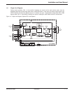
STS MONITOR
KEY INTERLOCKS
(2 - STANDARD
4 - OPTIONAL)
CB2
CB5
CB3A
CB3B
CB1
CB4