


Installation and User Manual
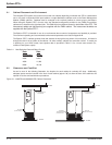
1.72 Electrical Cable Access and Connections
Electrical connections and other cabinet interconnection will vary depending upon the configuration and options
selected with your Epsilon STS™ system. Refer to the installation drawings supplied with your equipment.
CAUTION: Before making any electrical connections, verify that all circuit beakers
are in the "off" position. Customer-supplied upstream protective devices
and distribution circuits should be OFF.
Risk of Electric Shock. For Plus and Ultra configurations, the PMM
2
equipment receives power from more than one source. Disconnect all
sources to this equipment before servicing.
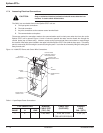
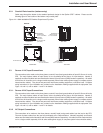
1.7.3 Connecting Power Cables
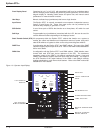
To access the connection terminal busbars, open the front door of the Epsilon STS™. Remove the screws securing
the swing-out control panel (upper panel in the 200A STS) and open it. Remove the safety panel located in the
upper left hand section of the unit.
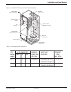
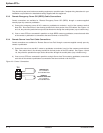
a) Connect the 3-phase, ground and neutral (if used) conductors of input AC
Source #1 to the Source #1 busbars.
b) Connect the 3-phase, ground and neutral (if used) conductors of input AC
Source #2 to the Source #2 busbars.
c) Connect the 3-phase, ground and neutral (if used) conductors supplying the load to the Output busbars.
d) Securely brace all cables at 12” intervals with cable ties.
e) Replace and secure all panels and covers back in place.rated voltage and tolerances
Introduction 1 — 986-504004-00 B03