


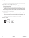
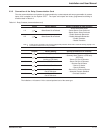
2.5 Setting the Output Relay Contacts and Input Switching States
Set DIP switch SA2 for one of the following configuration modes:
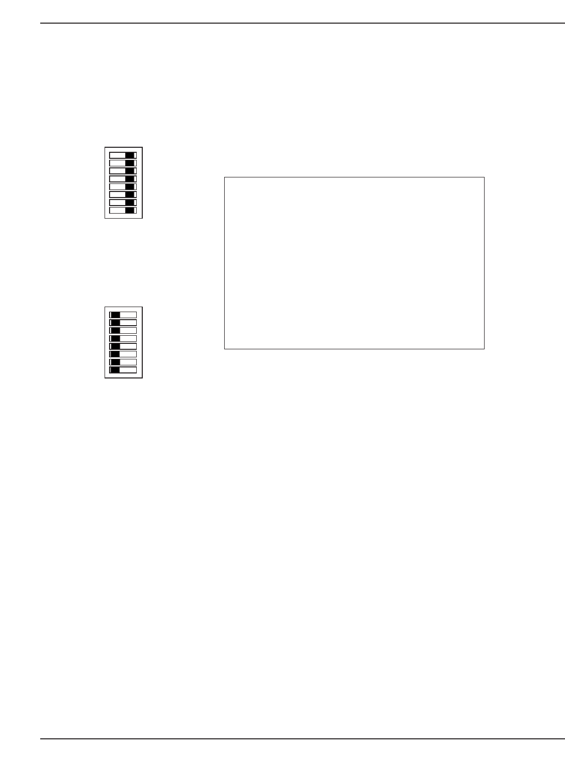
N.O. Setting (default)
All switches OFF
N.C. Setting
All switches ON
It is possible to individually set each relay and input to N.O. or N.C. mode by setting each switch on SA2 individu-
ally. The parameters for relays 1 to 6 are set using SA2 DIP switches 1 to 6 respectively. The parameters for inputs
A and B are set using SA2 DIP switches 7 and 8 respectively.
When the SA2 DIP switch is set to OFF, the relay/input is set to N.O.
When the SA2 DIP switch is set to ON, the relay/input is set to N.C.
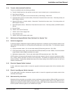
SA2
ON OFF
8
N.O.N.C.
1
Installation and User Manual
Installation 2 — 986-504004-00 B03
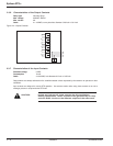
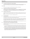
SA1
ON OFF
8
1
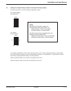
NOTE:
By default, all the relay contacts are
Normally Open (NO) (see section 1.4):
◗ Contact open = relay not controlled.
◗ Contact closed = relay controlled.
By default, the inputs are activated when the
external contact is closed (NO):
◗ External contact open = input not activated.
◗ External contact closed = input activated.