


Installation and User Manual
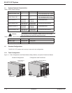
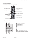
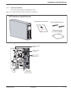
1.3.3 EX RT Transformer Module
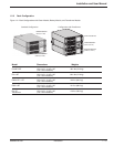
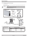
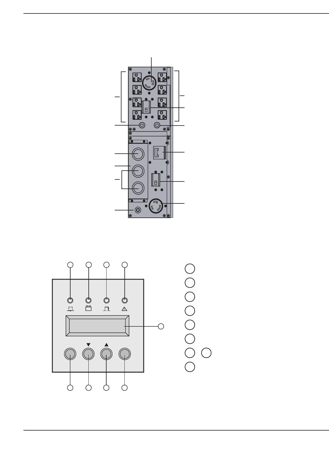
Figure 1-5: Rear Panel of the optional Transformer Module. (PN 86003)
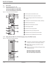
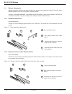
1.4 Display and Control Panel
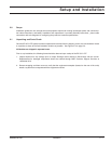
Figure 1-6: View of typical control panel interface.
Introduction 1 — 786-86000-00 A01
Main Output Circuit Breaker
Load 2: 4 NEMA 5-15/20R
Load 3 Circuit Breaker
Load 2 Circuit Breaker
Load 1: 1 NEMA L6-30R
Load 1 Circuit Breaker
Transformer Protect
Breaker
Load 4: 4 NEMA 5-15/20R
Load 4 Circuit Breaker
Transformer I/O Box
AC Input
AC Output
L
oa
d
3: 1
NEMA
L
6-30
R
OFF
ON
E X 1 1 R T
15 16
19
17 18
20 21 22 23
Load protected / On-line Operation LED.
Operation on battery LED.
Operation on bypass LED.
Fault LED.
Alphanumeric display.
UPS OFF button.
Function buttons (scroll up / scroll down).
UPS ON button (or function button in personalization
mode).
23
2221
20
19
18
17
16
15