


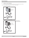
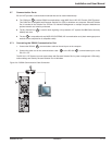
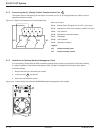
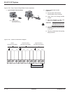
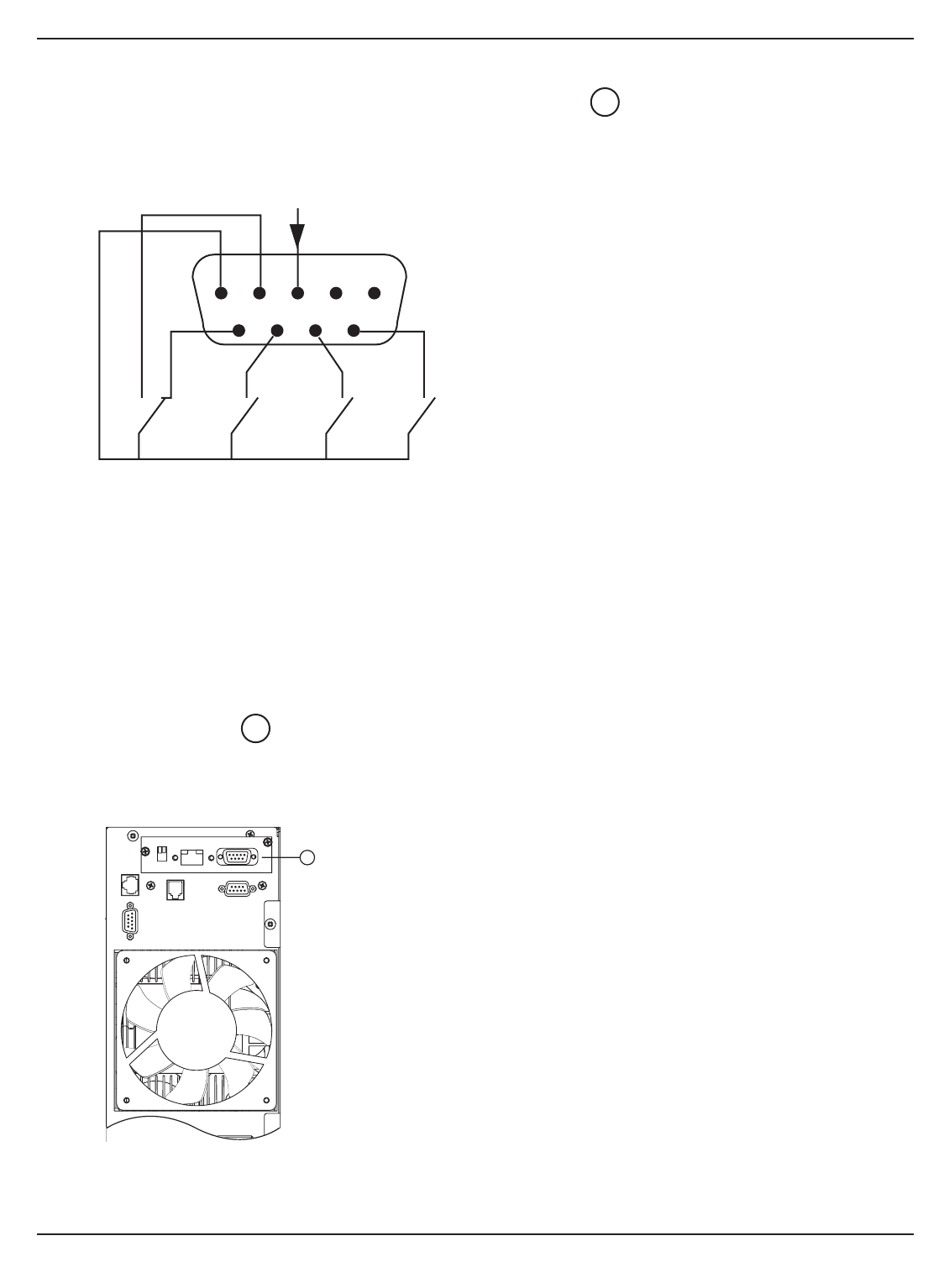
2.7.2 Connecting the Dry (Relay) Contact Communication Port
The system status is indicated by the connection of common pin (Pin 5) to the appropriate pins. Refer to the pin
explanations below for details.
Figure 2-9: Relay Pin Connections for Communication Port.
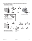
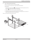
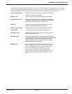
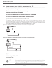
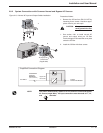
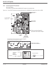
2.7.3 Installation of Optional Network Management Card
It is not necessary to shut down the UPS to install the optional communications card, except for USB card. Following
is a typical installation of the Network Management Card, (PN 66074, standard with the network pack option.)
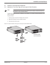
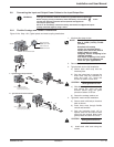
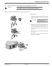
Proceed as follows:
1. Remove the slot cover secured by two screws.
2. Insert the card into the slot.
3. Secure the card with both screws.
Figure 2-10: Communication Card Slot with SNMP/Web Network Management Card installed.
37
2
EX 5/7/11 RT System
Installation2 — 10 86-86000-00 A01
123
45
6789
NONC NONO
common
NO
Pin 1, 2: not used.
Pin 3: Remote Power Off signal (5 to 27 VDC, 10 mA max).
Pin 4: Operation on mains (not on battery). (48VDC, 2A max.)
Pin 5: User common.
Pin 6: Operation on automatic bypass.
Pin 7: Low battery.
Pin 8: Load protected
Pin 9: Operation on battery.
Legend:
NO: contact normally open.
NC: contact normally closed.
37