


Installation and User Manual
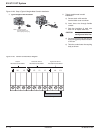
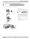
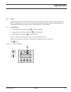
2.8.4 System Connections with Separate Normal and Bypass AC Sources
CAUTION: This installation requires 2 AC input source with Line, Neutral plus Ground,
(200-240VAC). Neutral points are connected together inside the UPS.
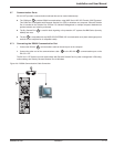
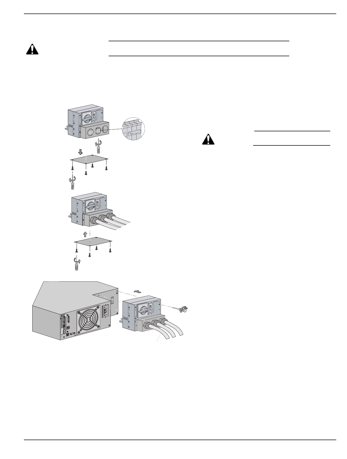
Figure 2-15: Normal AC Input, Bypass AC, and Output Cables Installation.
Installation 2 — 1786-86000-00 A01
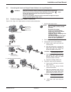
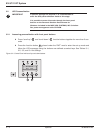
Proceed as follows:
1. Remove the cover plate under the I/O Box. Loosen
the terminal blocks L1 and L3, and remove the
jumper.
CAUTION: Always connect the
earth ground wire first.
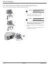
2. See section 2.8.1 and I/O Box terminal diagram for
installation of Normal AC Input, Bypass AC
source, and Output cable with different wire style.
3. Reinstall the cover plate under the I/O Box with
four screws.
4. Secure the I/O Box to the power module using
three screws.
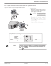
See section 2.8.3 for connecting EX RT
Transformer, if applicable.
4
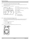
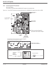
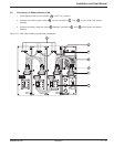
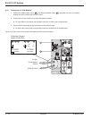
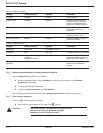
Card Settings
RS232 Download
66074
UPS
data
Reset
100 10
1 2
ON
ETHERNET
IP=
MAC=00E0D8FF855E
1
3
Output
Bypass
Normal
L1
L3
O
F
F
O
O
F
F
O
O
F
F
O
To Step-Down
Transformer
(if applicable)
2