


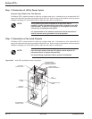

Step 2 Connection of Utility Power Inputs
Connect Input Power from Two Sources
The Epsilon STS™ systems provides for either top or bottom cable entry. Connections are to be made with 75°C
copper wire cables and using the lugs supplied with the STS unit. Refer to section 2.0 Installation and/or the system
installation drawing(s) for more details (such as cable size and number of conductors).
NOTE:
Three phase input power supplied as a Wye must have a
separate, solidly
grounded neutral that will be connected to the STS
neutral busbar. If neutral is not supplied or not required for the load,
connect only three phases and ground.
It is recommended to use isolation transformers so that the neutral of
both AC sources can be grounded to the same potential.
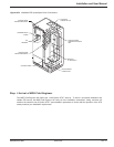
Step 3 Connection of the Load Outputs
The Epsilon STS™ system provides for either top or bottom cable entry. Connections are to be made with 75°C
copper wire cables and using the lugs supplied with the STS unit. Refer to section 2.0 Installation and/or the system
installation drawing(s) for more details (such as cable size and number of conductors).
NOTE:
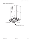
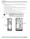
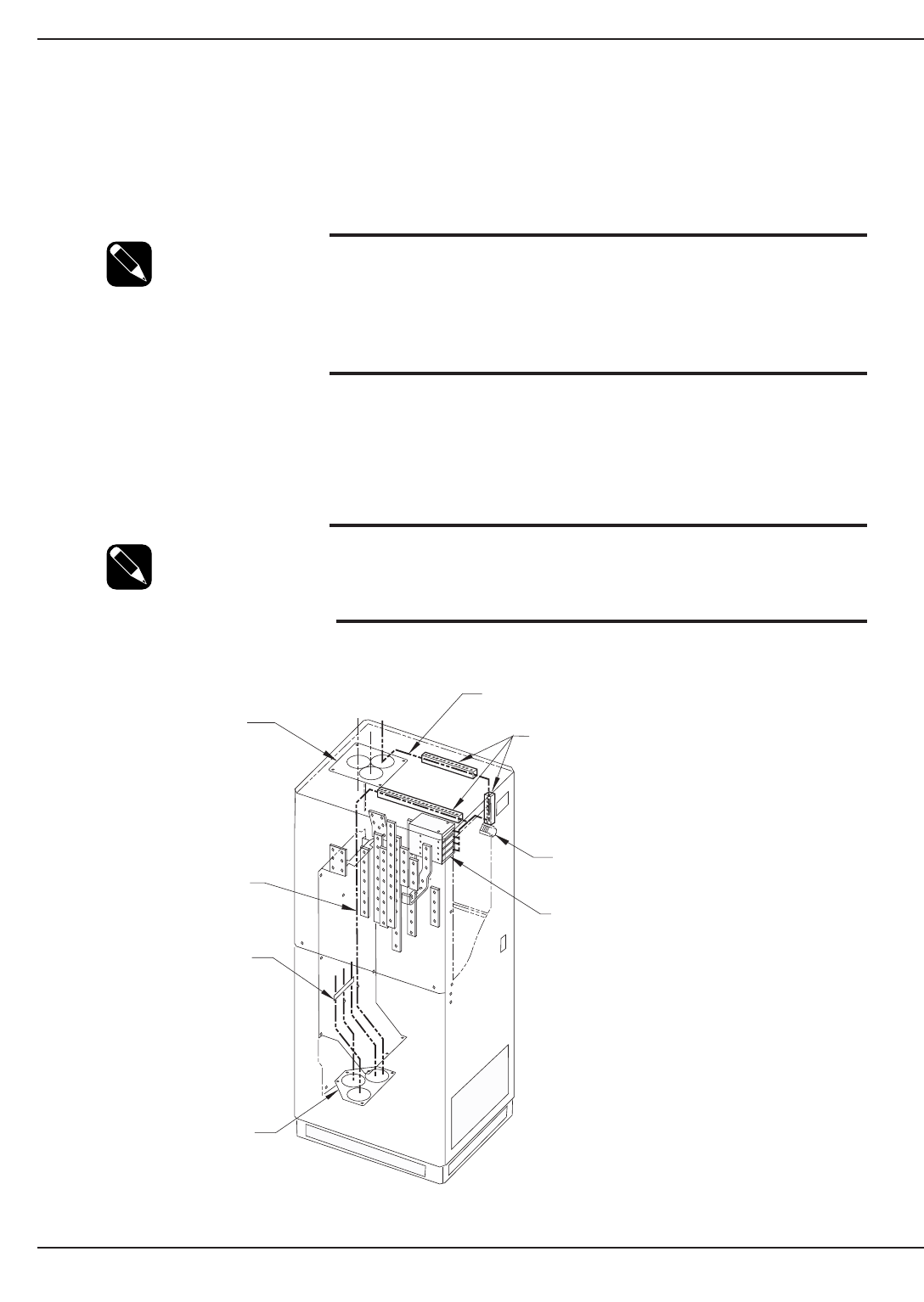
Input and output cables inside the STS cabinet must be braced at 12”
intervals
as shown in Figures QS-3 and QS-4.
For Control Wiring connections refer to section 2.0 Installation.
Figure QS-3 200A STS Input/Output Power Connections.
Epilson STS
TM
Quick startQS —4 86-504004-00 B03
COMMUNICATION
CARDS
TB1
TERMINAL
CONTROL WIRES
THREADED THROUGH
PANDUIT/WIRE-WAYS
TOP ENTRY
CONDUIT PLATE
CONTROL
WIRES
BRACE AT
12" INTERVALS
BOTTOM ENTRY
CONDUIT PLATE
CONTROL WIRE
PANDUIT/WIRE-WAYS