


Contents
Contents
c i86-504004-00 B03
section description . . . . . . . . . . . . . . . . . . . . . . . . . . . . . . . . . . . . . . . . . . .page
Revision History . . . . . . . . . . . . . . . . . . . . . . . . . . . . . . . . . . . . . . . . . .i
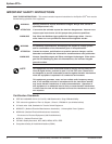
IMPORTANT SAFETY INSTRUCTIONS . . . . . . . . . . . . . . . . . . . . . . .ii
Certification Standards . . . . . . . . . . . . . . . . . . . . . . . . . . . . . . . . . . . .ii
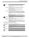
How to use this manual and Symbol Usage . . . . . . . . . . . . . . . . . . . .iii
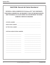
CAUTION: Record All Serial Numbers! . . . . . . . . . . . . . . . . . . . . . . .iv
Quick Start
section description . . . . . . . . . . . . . . . . . . . . . . . . . . . . . . . . . . . . . . . . . . .page
First steps by an on-site qualified Technical Engineer . . . . . . . . . . . . .QS —1
Required Equipment and Tools . . . . . . . . . . . . . . . . . . . . . . . . . . . . . . .QS —1
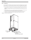
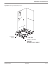
Step 1 Unpacking . . . . . . . . . . . . . . . . . . . . . . . . . . . . . . . . . . . . . . .QS —2
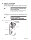
Step 2 Connection of Utility Power Inputs . . . . . . . . . . . . . . . . . . . . .QS —4
Connect Input Power from Two Sources . . . . . . . . . . . . . . . .QS —4
Step 3 Connection of the Load Outputs . . . . . . . . . . . . . . . . . . . . . .QS —4
Step 4 Call MGE UPS Systems for Field Engineer Service . . . . . .QS —5
Step 5 Arrival of MGE Field Engineer . . . . . . . . . . . . . . . . . . . . . . . .QS —5
Optional Steps . . . . . . . . . . . . . . . . . . . . . . . . . . . . . . . . . . . . . . . . . . . .QS —6
Section 1 Introduction
section description . . . . . . . . . . . . . . . . . . . . . . . . . . . . . . . . . . . . . . . . . . .page
1.0 Scope . . . . . . . . . . . . . . . . . . . . . . . . . . . . . . . . . . . . . . . . . . . . .1 — 1
1.1 Reference Manuals . . . . . . . . . . . . . . . . . . . . . . . . . . . . . . . . . . .1 — 1
1.2 Section Descriptions . . . . . . . . . . . . . . . . . . . . . . . . . . . . . . . . . .1 — 1
1.3 General Description . . . . . . . . . . . . . . . . . . . . . . . . . . . . . . . . . . .1 — 2
1.4 Epsilon STSTM System Characteristics . . . . . . . . . . . . . . . . . . .1 — 3
1.4.1 PMM2 Plus and PMM2 Ultra . . . . . . . . . . . . . . . . . . . . . . . . . . . .1 — 4
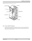
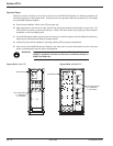
1.5 System Major Components . . . . . . . . . . . . . . . . . . . . . . . . . . . . .1 — 5
1.6 Single Line Diagram . . . . . . . . . . . . . . . . . . . . . . . . . . . . . . . . . .1 — 7
1.7 System Specifications . . . . . . . . . . . . . . . . . . . . . . . . . . . . . . . . .1 — 8
1.7.1 Electrical Electrical Characteristics . . . . . . . . . . . . . . . . . . . . . . .1 — 8
1.7.2 Electrical Cable Access and Connections . . . . . . . . . . . . . . . . . .1 — 9
1.7.3 Connecting Power Cables . . . . . . . . . . . . . . . . . . . . . . . . . . . . .1 — 9
1.7.4 Accessing Electrical Connections . . . . . . . . . . . . . . . . . . . . . . .1 — 10