


Installation and User Manual
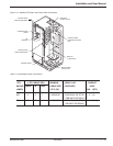
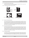
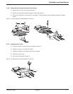
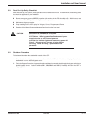
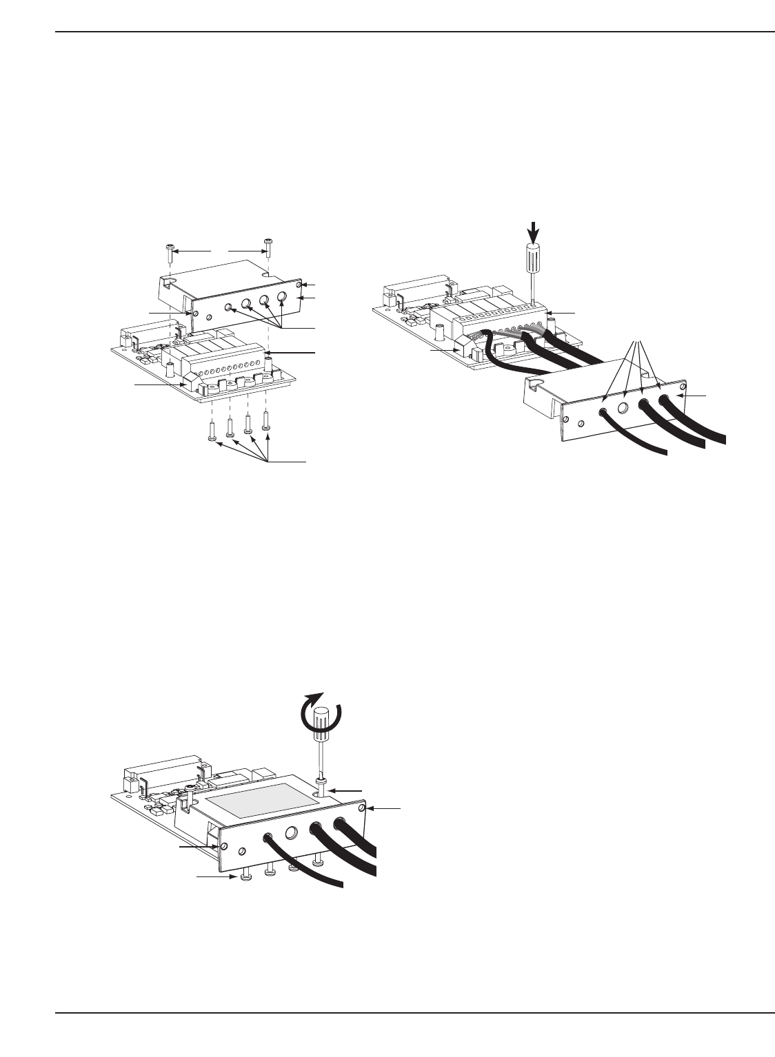
2.3.8 Removing the Communications Card Cover
a) Remove the cover “3” secured by the screws “1”.
b) Run the communications cables through the cable entry holes “4”.
c) Connect the conductors to the input “6” and output “5” terminal blocks (see connection example in diagram
below).
Figure 2-5: Removing the Communications Card Cover.
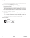
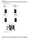
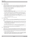
2.3.9 Replacing the Cover
d) Put the cover back in place and secure it with the screws “1”.
e) Tighten the screws “7” to clamp the cables.
f) Indicate the locations of the power sources on the labels.
g) Insert the card in its slot.
h) Secure the card with two screws “2”.
Figure 2-6: Replacing the Communications Card Cover.
Installation 2 — 786-504004-00 B03
1
2
3
4
5
6
A
B
1
2
3
2
5
7
6
4
1
2
3
4
5
6
A
B
4
3
5
6
1
2
2
7