


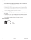
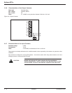
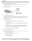
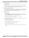
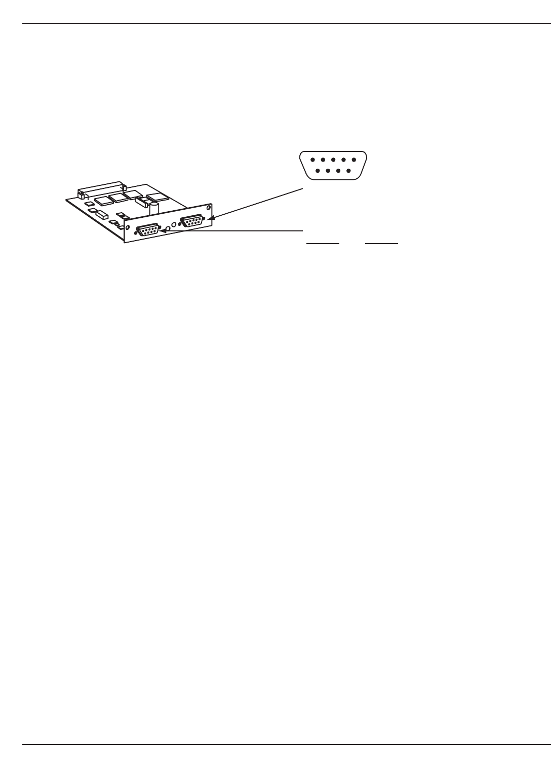
2.5.1 Connection of the JBUS Communication Card
The JBUS communications card provides two DB-9 ports (RS232 and RS485 communications). Only one commu-
nication port may be used at a time.
For information on using the communication card, see the JBUS communication card manual.
Figure 2-8: JBUS Communication Card.
2.6 Check Points Before and After Start Up
Before starting the Epsilon STS™, be certain that you fully understand the operation of the indicators, controls, and
operational sequences. MGE UPS SYSTEMS,INC. offers professional start up services in most countries. It is
suggested that before applying power to your Epsilon STS™, your contract with MGE for a professional start up with
an MGE Field Engineer.
2.6.1 Pre-Start Up Safety Check List
◗ All power and control wires have been properly connected and securely tightened.
◗ The upstream and downstream protective devices are not tripped, and have been sized properly for the
STS and load requirements.
◗ The input voltage is the same as indicated on the STS nameplate, located inside the door of the Epsilon
STS™ module.
◗ The air filters located inside the STS module door (400/600A units only) are properly installed and free of
dust, dirt, and debris. Make certain that no objects block the air intake underneath and around the front
bottom of the STS module and the air exhaust on the top of the STS module is free of obstructions.
◗ All switches in the STS, CB1-5, are in the OFF (open) position.
◗ All panels and covers are replaced and secured back in place.
2.6.2 Post-Start Up Safety Check List
After initial start-up of the system, normal operation should be tested. At the minimum, the following tests should
be performed as applicable to your installation.
◗ Emergency power off (EPO) test.
◗ Remote emergency power off (REPO) test (if applicable).
◗ STS start up on preferred source.
◗ Transfer test on preferred source loss.
◗ Maintenance bypass procedure.
Epilson STS
TM
Installation2 — 10 86-504004-00 B03
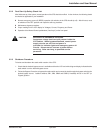
JBUS/MODBUS
54321
9876
RS232:
Pin 2: Rxd (or Txd)
Pin 3: Txd (or Rxd)
Pin 5: Com (shield)
RS485:
JBUS
Pin 4: Rx-
Pin 5: Tx-
MODBUS
Pin 8: Rx+
Pin 9: Tx+