


Epilson STS
TM
Contentsc ii 86-504004-00 B03
Section 2 Setup and Installation
section description . . . . . . . . . . . . . . . . . . . . . . . . . . . . . . . . . . . . . . . . . . .page
2.0 Scope . . . . . . . . . . . . . . . . . . . . . . . . . . . . . . . . . . . . . . . . . . . . .2 — 1
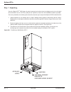
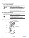
First steps by an on-site qualified Technical Engineer . . . . . . . .2 — 1
Final steps by MGE Field Service Engineer . . . . . . . . . . . . . . . .2 — 1
Required Equipment and Tools . . . . . . . . . . . . . . . . . . . . . . . . . .2 — 1
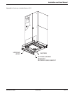
2.1 Cabinet Placement and Environment . . . . . . . . . . . . . . . . . . . . .2 — 2
2.2 Clearances and FootPrint . . . . . . . . . . . . . . . . . . . . . . . . . . . . . .2 — 2
2.2.1 Conduit Plate Location (bottom entry) . . . . . . . . . . . . . . . . . . . . .2 — 3
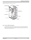
2.3 Source #1 AC Input Connections . . . . . . . . . . . . . . . . . . . . . . . .2 — 3
2.3.1. Source #2 AC Input Connections . . . . . . . . . . . . . . . . . . . . . . . .2 — 3
2.3.2 AC Output Connections . . . . . . . . . . . . . . . . . . . . . . . . . . . . . . . .2 — 3
2.3.3 Remote Emergency Power Off (REPO) Cable Connections . . .2 — 4
2.3.4 Remote Source Loss Test Cable Connections . . . . . . . . . . . . . .2 — 4
2.3.5 Connection of the Relay Communication Card . . . . . . . . . . . . . .2 — 5
2.3.6 Characteristics of the Output Contacts . . . . . . . . . . . . . . . . . . . .2 — 6
2.3.7 Characteristics of the Input Contacts . . . . . . . . . . . . . . . . . . . . .2 — 6
2.3.8 Removing the Communications Card Cover . . . . . . . . . . . . . . . .2 — 7
2.3.9 Replacing the Cover . . . . . . . . . . . . . . . . . . . . . . . . . . . . . . . . . .2 — 7
2.4 Setting Operation Mode . . . . . . . . . . . . . . . . . . . . . . . . . . . . . . .2 — 8
2.5 Setting the Output Relay Contacts and Inputs Switching States 2 — 9
2.5.1 Connection of the JBUS Communication Card . . . . . . . . . . . . .2 — 10
2.6 Check Points Before and After Start Up . . . . . . . . . . . . . . . . . .2 — 10
2.6.1 Pre-Start Up Safety Check List . . . . . . . . . . . . . . . . . . . . . . . .2 — 10
2.6.2 Post-Start Up Safety Check List . . . . . . . . . . . . . . . . . . . . . . . .2 — 10
Section 3 Operation
section description . . . . . . . . . . . . . . . . . . . . . . . . . . . . . . . . . . . . . . . . . . .page
3.0 Scope . . . . . . . . . . . . . . . . . . . . . . . . . . . . . . . . . . . . . . . . . . . . . .3 —1
3.1 Preparation for Operation . . . . . . . . . . . . . . . . . . . . . . . . . . . . . . .3 —1
3.2 Pre-Start Up Safety Check List . . . . . . . . . . . . . . . . . . . . . . . . . .3 —1
3.2.1 Normal Start Up Procedure . . . . . . . . . . . . . . . . . . . . . . . . . . . . .3 —2
3.2.2 Post Start Up Safety Check List . . . . . . . . . . . . . . . . . . . . . . . . . .3 —3
3.2.3 Shutdown Procedure . . . . . . . . . . . . . . . . . . . . . . . . . . . . . . . . . .3 —3
3.3 Transfer Operations . . . . . . . . . . . . . . . . . . . . . . . . . . . . . . . . . . .3 —4
3.3.1 Automatic Transfers . . . . . . . . . . . . . . . . . . . . . . . . . . . . . . . . . . .3 —4
3.3.2 Manual Transfers . . . . . . . . . . . . . . . . . . . . . . . . . . . . . . . . . . . . .3 —4
3.3.3 Automatic Retransfers . . . . . . . . . . . . . . . . . . . . . . . . . . . . . . . . .3 —4
3.3.4 Transfer Authorization/Prohibition . . . . . . . . . . . . . . . . . . . . . . . . .3 —5
3.4 Maintenance Bypass/Molded Case Switches/Live System Test .3 —5
3.4.1 Switch Arrangement . . . . . . . . . . . . . . . . . . . . . . . . . . . . . . . . . . .3 —5
3.4.2 Electrical Bypass Switch Interlock . . . . . . . . . . . . . . . . . . . . . . . .3 —5
3.4.3 Electric Input-Bypass Switch Interlock . . . . . . . . . . . . . . . . . . . . .3 —5
3.4.4 Mechanical Key Interlocks . . . . . . . . . . . . . . . . . . . . . . . . . . . . . .3 —5
3.4.5 Live System Test (Except with 4-Interlock System) . . . . . . . . . . .3 —6