


2. Installation
Safety Precautions
This section contains important safety and regulatory information that should be reviewed before installation
and use. For input and output current ratings, see Power Ratings in Technical Specifications.
Only for installation and use in a
Service Access Location in accordance
with the following installation and use
instructions.
Destiné à l'installation et l'utilisation
dans le cadre de Service Access
Location selon les instructions
d'installation et d'utilisation.
Nur für Installation und Gebrauch an
Anschlusszugriffspunkten gemäß der
folgenden Installations- und
Gebrauchsanweisungen.
This equipment is designed to be
installed on a dedicated circuit.
Cet équipement est conçu à être
installé sur un circuit spécialisé.
Diese Ausrüstung ist zur Installation in
einem festen Stromkreis vorgesehen.
Dedicated circuit must have circuit
breaker or fuse protection.
Switched PDUs have been designed
without a master circuit breaker or fuse
to avoid becoming a single point of
failure. It is the customer’s
responsibility to provide adequate
protection for the dedicated power
circuit. Protection of capacity equal to
the current rating of the Switched PDU
must be provided and must meet all
applicable codes and regulations. In
North American, protection must have a
10,000A interrupt capacity.
Le circuit spécialisé doit avoir un
disjoncteur ou une protection de
fusible. Des Switched PDUs ont été
conçus sans disjoncteur général ni
fusible pour éviter que cela devient un
seul endroit de panne. C’est la
responsabilité du client de fournir une
protection adéquate pour le circuit-
alimentation spécialisé. Protection de
capacité équivalant à la puissance de
l'équipement, et respectant tous les
codes et normes applicables. Les
disjoncteurs ou fusibles destinés à
l'installation en Amérique du Nord
doivent avoir une capacité
d'interruption de 10.000 A.
Der feste Stromkreis muss mit einem
Schutzschalter oder einem
Sicherungsschutz versehen sein.
Ein Switched PDU verfügt über keinen
Hauptschutzschalter bzw. über keine
Sicherung, damit kein einzelner
Fehlerpunkt entstehen kann. Der
Kunde ist dafür verantwortlich, den
Stromkreis sachgemäß zu schützen.
Der Kapazitätsschutz entspricht der
aktuellen Stromstärke der Geräte und
muss alle relevanten Codes und
Bestimmungen erfüllen. Für Installation
in Nordamerika müssen Ausschalter
bzw. Sicherung über 10.000 A
Unterbrechungskapazität verfügen.
The plug on the power supply cord
shall be installed near the equipment
and shall be easily accessible.
La prise sur le cordon d’alimentation
sera installée près de l’équipement et
sera facilement disponible.
Der Stecker des Netzkabels muss in
der Nähe der Ausrüstung installiert
werden und leicht zugänglich sein.
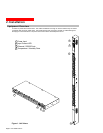
Installation Orientation: RSxx-Txxxx-x
units are design to be installed in
vertical orientation.
Installation Orientation : Les unités
RSxx-Txxxx-x sont conçues pour être
installées dans une orientation
verticale.
Installationsausrichtung: RSxx-Txxxx-x
Einheiten sind zur vertikalen Installation
vorgesehen.
Always disconnect the power supply
cord before opening to avoid electrical
shock.
Toujours déconnecter le cordon
d’alimentation avant d’ouvrir pour
éviter un choque électrique.
Ziehen Sie vor dem Öffnen immer das
Netzkabel heraus, um die Gefahr eines
elektrischen Schlags zu vermeiden.
WARNING! High leakage current!
Earth connection is essential before
connecting supply!
ATTENTION ! Haut fuite très
possible ! Une connection de masse
est essentielle avant de connecter
l’alimentation !
ACHTUNG! Hoher Verluststrom! Ein
Erdungsanschluss ist vor dem
Einschalten der Stromzufuhr
erforderlich!
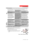
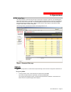
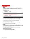
Installing the Power Input Retention Bracket
For Switched PDUs with a total maximum output <30A, it may be
necessary to install the power input retention bracket prior to mounting
the Switched PDU within the rack.
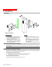
To install the power input retention bracket:
1. Remove the two screws attaching the IEC 60320 C19 inlet to the
enclosure.
2. Assemble and attach the retention bracket to the enclosure as
shown.
Figure 2. Retention Bracket assembly
301-0399-4 Rev A. - Page 7