


2. Installation
Mounting
Horizontal/Rack
e appropriate bracket mounting points
within the rack.
ts to these mounting points
Vertical
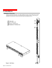
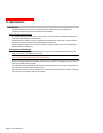
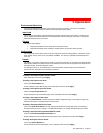
Figure 3. Mounting
1. Attach the removable flanges to the mount
r of the enclosure using M4
.
1. Select th
for proper mounting depth
2. Attach the bracke
with two screws for each bracket.
3. Install the enclosure into your rack, using the
slots in each bracket. The slots allow about ¼
inch of horizontal adaptability to align with the
mounting holes of your rack.
points on the rea
screws.
2. Attach the mounting L-brackets to the flanges
with the supplied screws, washers and nut
plates. The slots allow about 1½ inches of
vertical adaptability.
3. Attach the top and bottom brackets to your rack
Attac
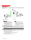
C nsion Module with the prov
hing the Expansion Module
onnect the Switched PDU Expa ided RJ12 crossover cable at the at the Link port on
the Switched PDU.
NOTE: The overall length of the cable should not exceed 10 feet.
Con e Power Source
en each outlet, eliminating a potential blown
ush current.
on bracket.
necting to th
Each outlet powers up sequentially, with a two-second delay betwe
primary fuse or circuit breaker from excessive in-r
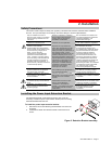
To attach a power cord to the unit:
1. Plug the female end of the power cord firmly into its connector at the base.
2. Use a screwdriver to tighten the two screws on the retenti
To connect to the power source:
Plug the male end of the power cord into the AC power source.
Page 8 - 301-0399-4 Rev A.