M54E2 System Board Manual
Section 2: Configuring the M54E2
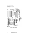
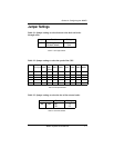
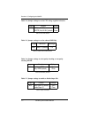
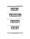
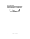
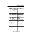
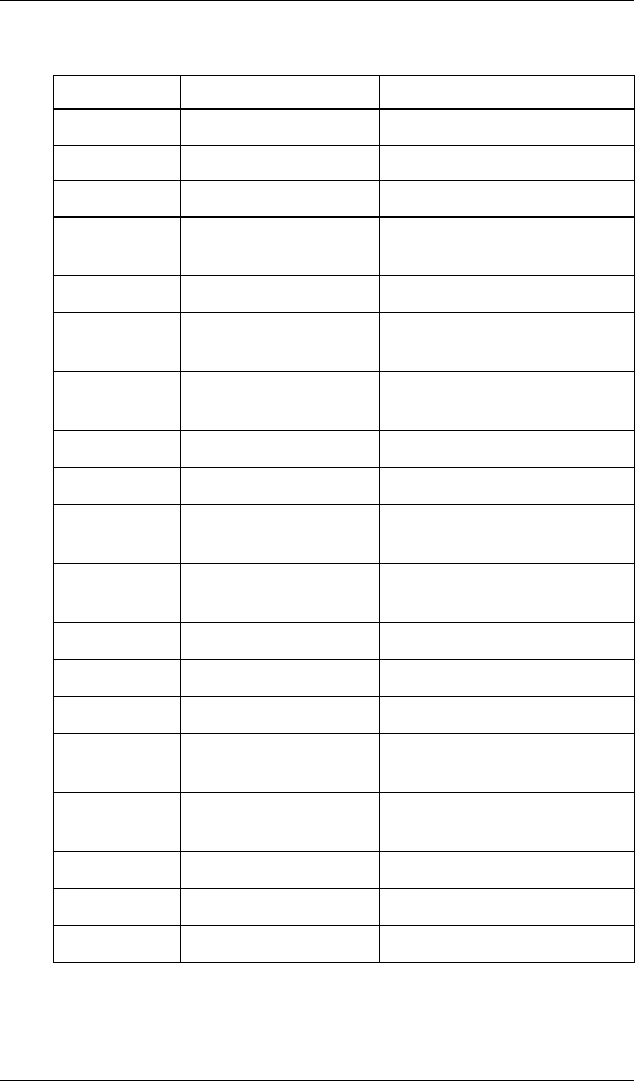
Table 2-13: Case and peripheral connections.
2-7
Connectors Function Notes
J1 & J2 Power Supply Connector
J5 AT Keyboard
J6 & J8 PS/2 Mouse & Keyboard PS/2 Version Only
J9 Parallel Port Connector Can be disabled at the CMOS
configuration screen
J10 Floppy Connector
J11 Serial Port (COM 1) Can be disabled at the CMOS
configuration screen
J12 Serial Port (COM 2) Can be disabled at the CMOS
configuration screen
J13 ISA IDE Connector Secondary
J25 Reserved Not Supported
J26 Optional Power Supply
Connector
For specially equipped power
supplies
W12 or W31 Speaker Connector 1 - Speaker, 2 - N/C, 3 - Ground
,
4 - 5V DC
W13 or W32 Reset
W14 or W33 Turbo LED 1 - +5V DC, 2 - Ground
W15 or W34 Turbo Switch
W18 or W37 Keylock/Power LED 1 - Speaker, 2 - N/C, 3 - Groun
d
4 - Keyboard Lock, 5 - Ground
W19 External Keyboard 1 - Clock (Keybd), 2 -Data,
3 - N/C, 4 - Ground, 5 - VCC
W24 or W38 Hard Disk LED 1 - +5V DC, 2 - Ground
W35 12V Fan Connector 1 - +12V DC, 2 - Ground
W36 12V Fan Connector 1 - +12V DC, 2 - Ground
Table 2-13: Case and Peripheral Connections


