


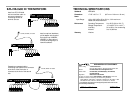
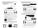
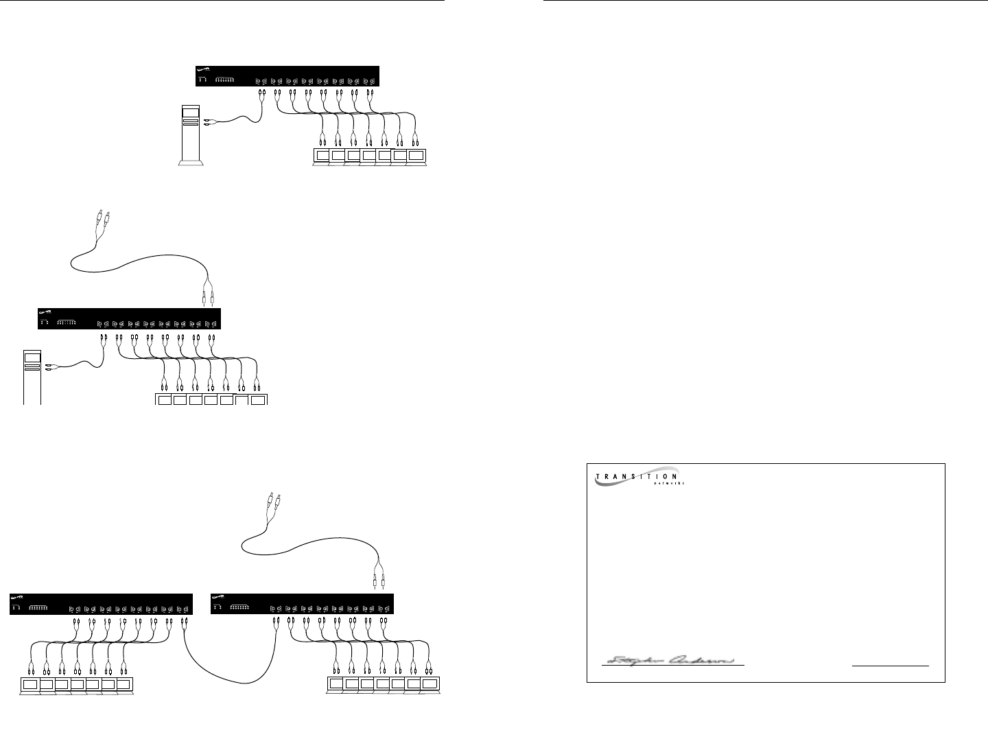
E-FL-HB-0x00 IN THE NETWORK
Install one E-FL-HB-0x00
hub and use fiber cable to
set up a workgroup by
connecting the hub to
terminal devices.
Install an optional backbone
uplink adaptor at the back of
the hub and use 10BASE-2,
10BASE-5, or fiber cable to
connect the workgroup to a
network backbone.
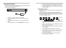
Cascade two repeater hubs by
connecting fiber cable from a connector
at the front of the first hub to a
connector at the front of the second
hub.
TECHNICAL SPECIFICATIONS
Standards IEEE 802.3
Dimensions 17.25" x 8.5" x 1.7" (437 mm x 216 mm x 43 mm)
Power
Input Range: 100 to 240 VAC at 50 or 60 Hz, 3.0 A maximum.
Rated at 40 watts maximum.
Environment Operating Temperature: 0° to 50°C (32° to 122° F )
Storage Temperature: -15° to 65°C (5° to 149° F )
Humidity 5% to 95%, non condensing
Altitude 0 to 10,000 feet
Warranty Lifetime
DECLARATION OF CONFORMITY
Name of Mfg: Transition Networks
6475 City West Parkway, Minneapolis MN 55344 USA
Model: E-FL-HB-0x00 Series Unmanaged Fiber Hub
Part Number: E-FL-HB-0800, E-FL-HB-0800(SC), E-FL-HB-0400,
E-FL-HB-0400(SC)
Regulation: EMC Directive 89/336/EEC
Purpose: To declare that the E-FL-HB-0800 or E-FL-HB-0400 to which this
declaration refers is in conformity with the following standards.
EMC-CISPR 22: 1985 Class A; EN 55022: 1988 Class A; EN 50082-1:1992;
EN 60950 A4:1997; IEC 801.2, IEC 801.3, and IEC 801.4; IEC 950
I, the undersigned, hereby declare that the equipment specified above conforms to the
above Directive(s) and Standard(s).
_November 10, 1999_____
Stephen Anderson, Vice-President of Engineering Date
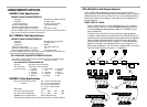
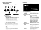
STAT
10BASE-FL
1
2
3
4
5
6
7
8
PWR
COL
ACT
BB
1
3
2
4
5
7
6
8
to hub, switch, or router
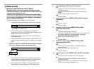
STAT
10BASE-FL
1
2
3
4
5
6
7
8
PWR
COL
ACT
BB
1
3
2
4
5
7
6
8
to hub, switch or router
STAT
10BASE-FL
1
2
3
4
5
6
7
8
PWR
COL
ACT
BB
1
3
2
4
5
7
6
8
STAT
10BASE-FL
1
2
3
4
5
6
7
8
PWR
COL
ACT
BB
1
3
2
4
5
7
6
8