


Power the E-FL-HB-0x00
NOTE: When the hub is connected to an AC outlet supplying 100-240VAC at
50-60 Hz, the hub automatically powers ON
To power ON the E-FL-HB-0x00:
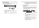
1. Locate power receptacle at back of E-FL-HB-0x00.
2. Plug unit end (female) of power cord into E-FL-HB-0x00 power
receptacle.
3. Plug outlet end (male) of power cord into correct voltage AC wall
socket.
4. At E-FL-HB-0x00 front, verify that P(o)W(e)R LED is illuminated.
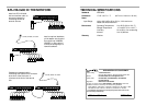
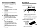
4. Connect AUI drop cable female connector to the AUI port on a
10BASE-5 cable transceiver or media attachment unit (MAU).
5. Verify that 10BASE-5 segment is terminated at both ends using
50-ohm terminators.
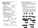
THROUGH BNC UPLINK
NOTE: Refer to 5-4-3 rule (page 3) to keep network configuration within
acceptable bounds.
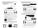
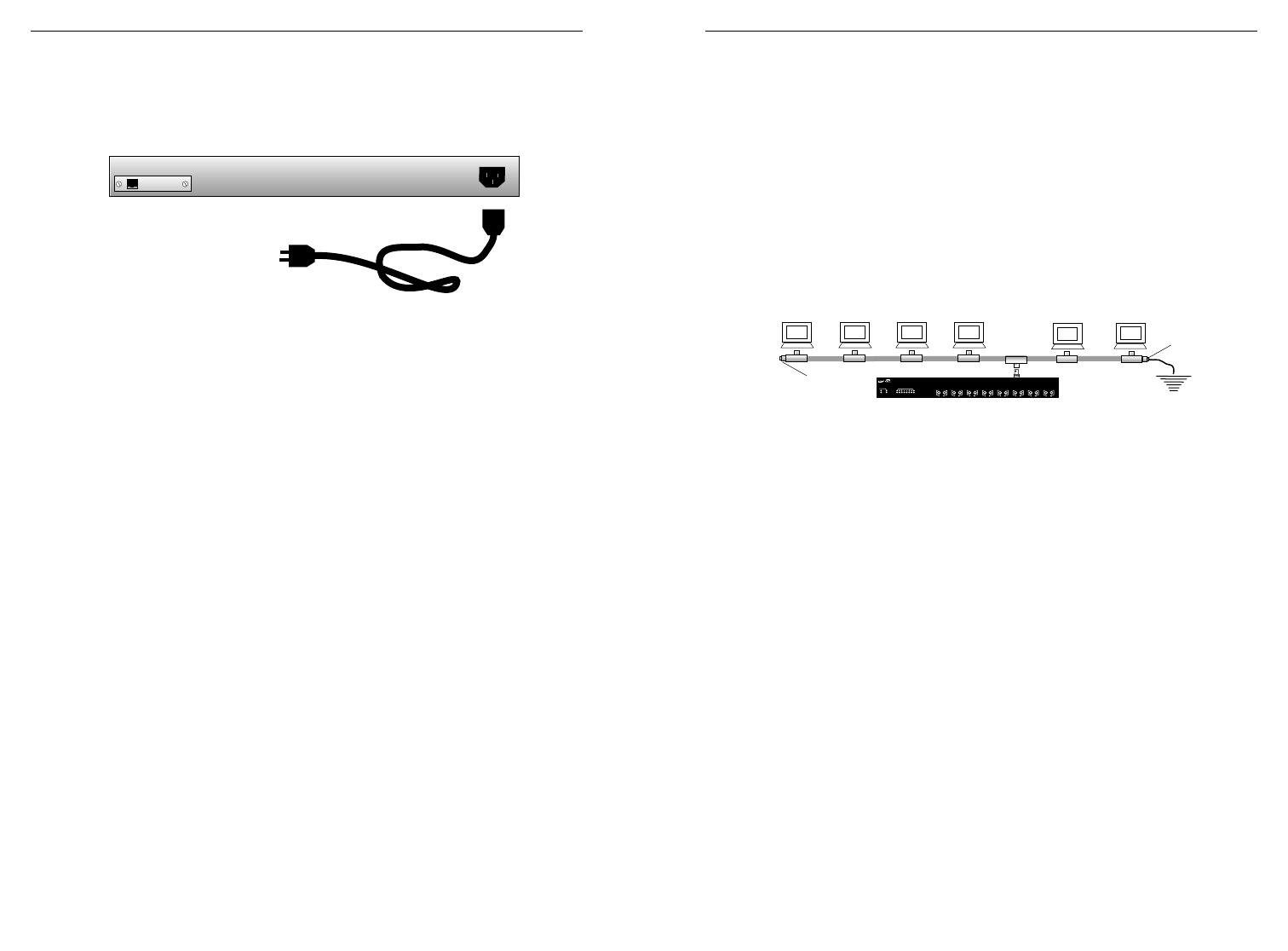
NOTE: In a coax thinnet installation, the first and last device in the
daisy-chain must be terminated using a 50 ohm terminator. Additionally,
the 10BASE-2 segment must be grounded to “earth ground” at one end.
To connect to 10BASE-2 network:
1. Locate BNC uplink adapter installed at E-FL-HB-0x00 back (See
page 4.)
2. Locate or build IEEE 802.3 compliant 10BASE-2 cable and male
BNC T-connector. (See page 14.)
3. Install the mating T-connector to the female BNC connector on
the E-FL-HB-0x00
4. Install 10BASE-2 cable at one side of the T-connector.
5. Install 10BASE-2 cable at other side of T-connector OR, if the
E-FL-HB-0x00 is the last network device in the daisy chain,
install 50-ohm terminator.
6. Verify that the 10BASE-2 segment coax cable segment is
terminated properly at both ends.
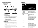
STAT
10BASE-FL
1
2
3
4
5
6
7
8
PWR
COL
ACT
BB
1
3
2
4
5
7
6
8
50Ω Terminator
Earth Ground
50Ω Terminator