


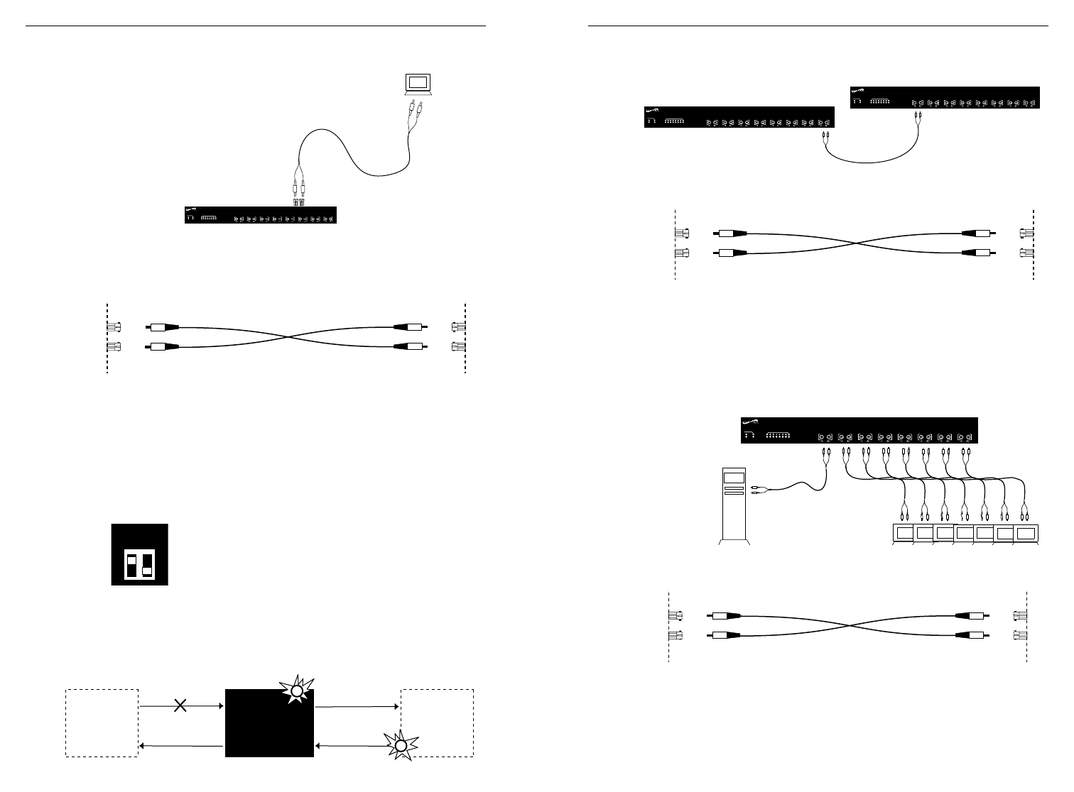
Optionally Connect to Backplane (continued)
THROUGH FIBER UPLINK
To connect fiber cable from E-FX-HB-xx00 10BASE-FL
uplink adapter to network:
1. Locate 10BASE-FL uplink adapter installed at E-FL-HB-0x00 back.
(See page 4.)
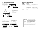
2. Locate or build 10BASE-FL compliant fiber cable with male two-
stranded TX to RX connectors at both ends. (See page 14.)
3. Connect male TX and RX cable connectors at one end of cable to
TX and RX female connectors, respectively, on E-FL-HB-0x00
10BASE-FL uplink adapter.
4. Connect male TX and RX cable connectors at other end of cable to
RX and TX connectors, respectively, on 802.3 compliant 10BASE-FL
network device.
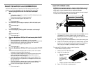
5. Set SWITCH 1 (located on the 10BASE-FL uplink adapter) to enable
or to disable the LinkALERT™ function.
(UP) Enables the LinkALERT
™ function. (DOWN)
Enables standard Link Integrity Test. Default is
LinkALERT
™ enabled (UP).
NOTE: SWITCH 2 is not used.
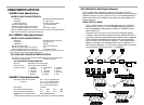
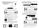
NOTE: The LinkAlert
™
feature allows each port to pass network link
faults over the port link. If the port does not detect a good link on
one side, the port disables all transmission (including active-idle) on
the other side.
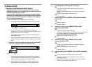
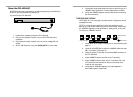
Optionally Cascade E-FL-0x00 Hubs
To cascade hubs by installing fiber cables between hubs:
1. Locate or build 10BASE-FL compliant two-stranded fiber cable with
appropriate male TX to RX connectors installed at both ends.
2. Connect male TX and RX cable connectors at one end of cable to
TX and RX female connectors, respectively, on front of one hub.
3. Connect male TX and RX cable connectors at other end of cable to
RX and TX connectors, respectively, on front of second hub.
Connect E-FL-0x00 Hub to Terminal Devices using Fiber
To connect fiber cable from E-FL-HB-0x00 ports to terminal devices:
1. Locate or build 10BASE-FL compliant two-stranded fiber cable with
appropriate male TX to RX connectors installed at both ends.
2. Connect male TX and RX cable connectors at one end of cable to
TX and RX female connectors, respectively, on E-FL-HB-0x00 port.
3. Connect male TX and RX cable connectors at other end of cable to
RX and TX connectors, respectively, on 802.3 compliant fiber
device.
4. Repeat steps 1-3 until all terminal devices are connected.
STAT
10BASE-FL
1
2
3
4
5
6
7
8
PWR
COL
ACT
BB
1
3
2
4
5
7
6
8
1 2
SWITCH
STAT
10BASE-FL
1
2
3
4
5
6
7
8
PWR
COL
ACT
BB
1
3
2
4
5
7
6
8
10BASE-FL
Device
E-FL-HB-0x00
Port
LINK FAULT INDICATION
10BASE-FL
Device
LINK FAULT INDICATION
STAT
10BASE-FL
1
2
3
4
5
6
7
8
PWR
COL
ACT
BB
1
3
2
4
5
7
6
8
STAT
10BASE-FL
1
2
3
4
5
6
7
8
PWR
COL
ACT
BB
1
3
2
4
5
7
6
8
TX
TX RX
RX
TX
TX
RX
RX
TX
TX RX
RX
TX
TX
RX
RX
TX
TX RX
RX
TX
TX
RX
RX