


FAULT ISOLATION and CORRECTION
If the E-FL-HB-0x00 fails, isolate and correct the fault by determining the
answers to the following questions and then taking the indicated action:
1. Is the P(o)W(e)R LED on the E-FL-HB-0x00 illuminated?
NO
• Is the power cord properly installed in the E-FL-HB-0x00 and in the
grounded AC outlet?
• Does the grounded AC outlet provide power?
• Contact Technical Support: (800) 260-1312.
YES
• Continue at step 2.
2. Is a backbone uplink adapter installed at E-FL-HB-0x00 back?
NO
• Continue at step 7.
YES
• Continue at step 3.
3. Is the B(ack)B(one) STAT(us) LED illuminated continuously?
YES
• Continue at step 7.
NO
• Continue at step 4.
4. Does the B(ack)B(one) STAT(us) LED continuously blink ONCE?
YES
• Ensure that backbone uplink adapter is firmly connected.
• Check backbone uplink cables for proper cabling and connection(s).
• Ensure that device at remote end of network link is powered.
• Contact Technical Support: (800) 260-1312.
NO
• Continue at step 5.
5. Does the B(ack)B(one) STAT(us) LED continuously blink TWICE?
YES
• If the AUI backbone adapter plate is installed, check the installed
transceiver or the drop cable connections.
• If the BNC backbone adapter plate is installed, ensure that coaxial
cable connections are secure and that daisy-chained cable is
terminated at both ends. (See page 7.)
• If the fiber backbone adapter plate is installed and LINKAlert™ is
NOT enabled, the port is partitioned; investigate the device at the
far end of the link..
• If the fiber backbone adapter plate is installed and LINKAlert™ IS
enabled, determine and correct the cause of the Far End Fault.
• Contact Technical Support: (800) 260-1312.
NO
• Continue at step 6.
Install E-FL-HB-0x00 at Site
WARNING: During the site installation, handle the E-FL-HB-0x00 in such a
way that the E-FL-HB-0x00 does not fall. Failure to observe this warning
could result in injury to personnel and/or equipment damage.
NOTE: If E-FL-HB-0x00 is shipped with brackets installed, proceed to step 2.
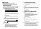
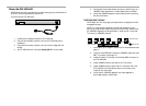
To install the E-FL-HB-0x00 in 19-inch rack cabinet:
1. Remove and retain two (2) screws located at front left side and front
right side of E-FL-HB-0x00 chassis. Install right and left front
brackets (provided) on chassis by installing two (2) retained screws
through each bracket into chassis.
2. Carefully align E-FL-HB-0x00 between 19-inch rack mounting rails.
3. Install E-FL-HB-0x00 by installing two (2) screws through right front
bracket into rack and two (2) screws through left front bracket into
rack, using clip nuts (NOT provided) to secure, if necessary.
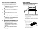
To install the E-FL-HB-0x00 on table or other flat surface:
NOTE: Rubber feet are provided.
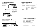
1. Carefully turn E-FL-HB-0x00 to side.
2. Install four (4) rubber feet:
• Separate rubber feet.
• Remove
protective paper
from adhesive
surface on rubber
foot.
• Position and secure each rubber foot as shown.
3. Return E-FL-HB-0x00 to upright position.
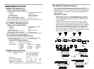
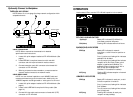
1
3
2
STAT
10BASE-FL
1
2
3
4
5
6
7
8
PWR
COL
ACT
BB
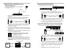
1
3
2
4
5
7
6
8