


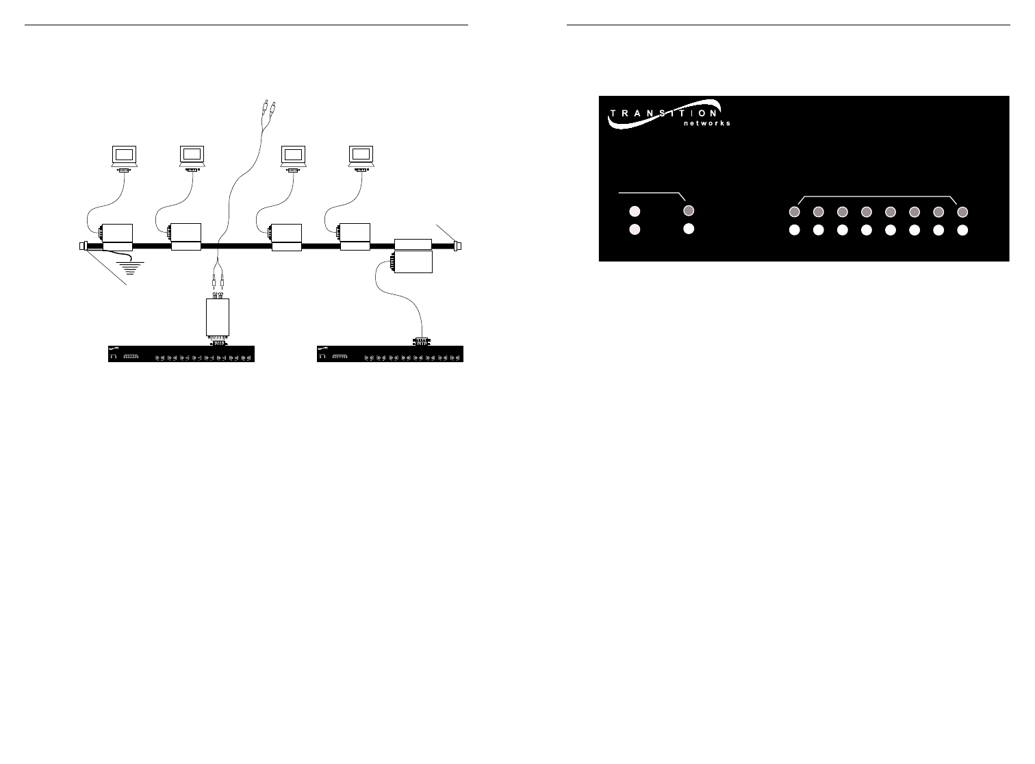
Optionally Connect to Backplane
THROUGH AUI UPLINK
NOTE: Refer to 5-4-3 rule (page 3) to keep network configuration within
acceptable bounds.
USING TRANSCEIVER
NOTE: Refer to transceiver documentation for detailed
specifications and instructions.
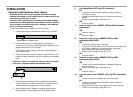
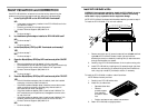
1. Locate AUI uplink adapter installed at E-FL-HB-0x00 back. (See
page 4.)
2. Locate IEEE 802.3 compliant transceiver with male AUI
connector and with required network media connector.
3. Connect transceiver male AUI connector to the female AUI
connector on E-FL-HB-0x00
4. Referring to transceiver documentation, connect transceiver
network media connector to the network media.
USING DROP CABLE
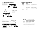
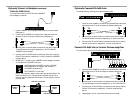
NOTE: In a coax thicknet installation, each 10BASE-5 cable end
must be terminated using a 50 ohm terminator. Additionally, the
10BASE-5 segment must be grounded to “earth ground” at one end.
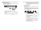
1. Locate AUI uplink adapter installed at E-FL-HB-0x00 back. (See
page 4.)
2. Locate or build IEEE 802.3 compliant AUI drop cable. (See
page 14.)
3. Connect AUI drop cable male connector to female AUI (DTE)
connector on E-FL-HB-0x00
OPERATION
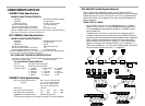
Use the status LEDs to monitor E-FL-HB-0x00 operation in the network.
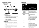
E-FL-0X00 HUB INDICATORS
P(o)W(e)R Steady LED indicates E-FL-HB-0x00 is
connected to external AC power.
COL(lision) Flashing LED indicates network collisions.
B(ACK)B(ONE) INDICATORS
STAT(us) Steady LED indicates, for network
connection, a valid link and no partition or
isolation.
One (1) continuous, flashing blink indicates
network link is down.
Two (2) continuous, flashing blinks indicate
reception of Far End Fault (if fiber uplink
adapter is installed and LINKAlert™ is
enabled) OR port is partitioned (if AUI or
BNC or fiber uplink adapter with
LINKAlert™ not enabled is installed).
ACT(ivity) Flashing LED indicates reception of network
data packet(s).
10BASE-FL INDICATORS
STAT(us) Steady LED indicates, for each port, a valid
link and no partition or isolation.
One (1) continuous, flashing blink indicates
link is down.
Two (2) continuous, flashing blinks indicate
port is partitioned.
ACT(ivity) Flashing LED indicates, for each port,
reception of data packet(s).
S TAT
10BASE-FL
1
2
3
4
5
6
7
8
PWR
COL
ACT
BB
STAT
10BASE-FL
1
2
3
4
5
6
7
8
PWR
COL
ACT
BB
1
3
2
4
5
7
6
8
STAT
10BASE-FL
1
2
3
4
5
6
7
8
PWR
COL
ACT
BB
1
3
2
4
5
7
6
8
50Ω Terminator
Earth Ground
50Ω Terminator