


USER GUIDE
6
7.1 LED and button table
LED Function
Power Power Indicator
Link Unit is connected to the network
Remote 1 & 2 Illuminates when a remote session is active
Power
POWER
100-240 VAC 50/60 Hz
Server ports
I
0
1 2 3 4 5 6 7 8
Keyboard
Mouse
Monitor
LOCAL USER
LAN (Ethernet)
port
LAN
SERIAL 1
Serial 1 port
10 11 12 13 14 15 169
SERIAL 2
SERVER
Serial 2 port
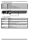
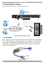
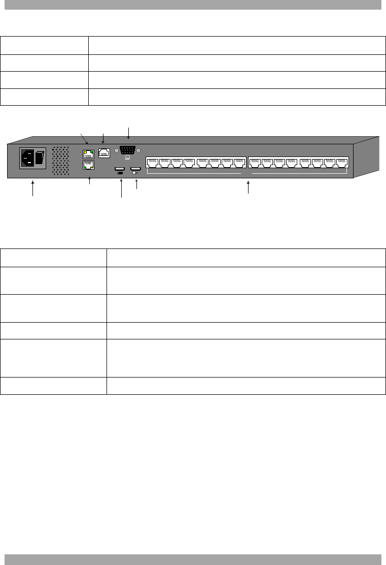
Figure 2 Smart 216 IP ports – side 2
7.2 Connector table
Connector Function
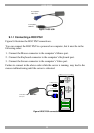
Console KVM Connect a keyboard, video and mouse to operate the Smart 216
IP locally
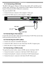
Serial 1 Connect any Serial device. Note! Minicom’s Serial Remote Power
Switch must be connected to Serial 1
Serial 2 Connect any Serial device.
LAN Connect to 10/100 Mbit Ethernet. Yellow Led illuminates when
connected to LAN. Green LED illuminates when a remote session
is in progress
Server ports Connect to servers via ROCs