22
I
* It shows the UPS is providing power to the “load”.
3.6.3 Measured Values detected by UPS
3.6.3.1 If you would like to check the measured values detected by the UPS,
please use the scroll down
and scroll up keypads. When you use
scroll down keypad, the LCD display will display the drawings in the
following order:
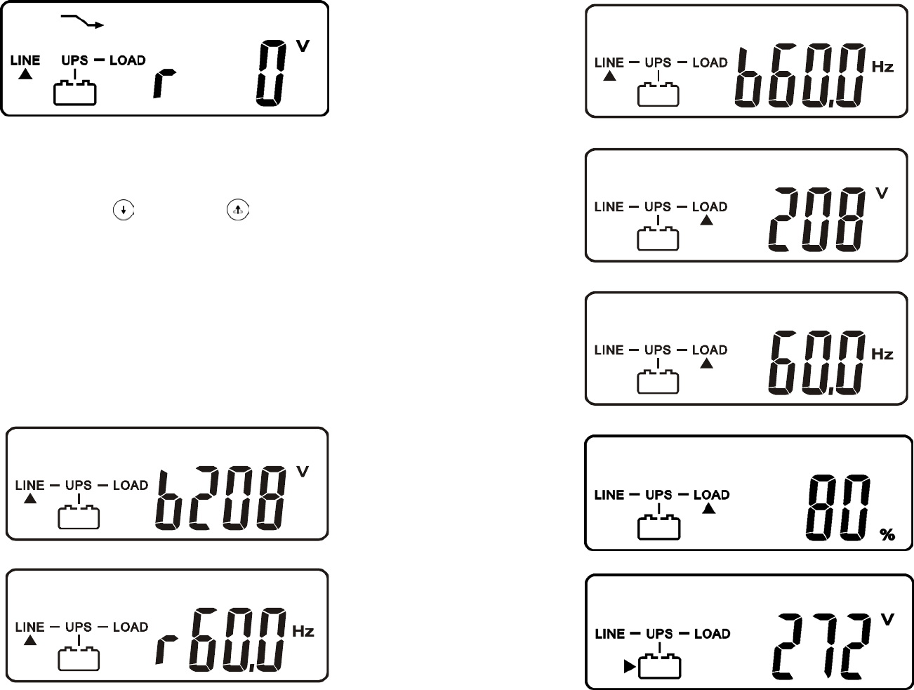
Drawing C (Voltage from Utility Input)
Drawing I1 (Voltage from Bypass Input)
Drawing J (Frequency from Utility Input)
Drawing K (Frequency from Bypass Input)
Drawing L (UPS Output Voltage)
Drawing M (UPS Output Frequency)
Drawing N (UPS Output Load %)
Drawing O (UPS Battery Voltage)
Drawing P (UPS Internal Temperature)
I1
* It shows the input voltage from the Bypass Input.
J
* It shows the input frequency from the Utility Input.
23
K
* It shows the input frequency from the Bypass Input.
L
* It shows the Output Voltage from the Inverter.
M
* It shows the Output Frequency from the Inverter.
N
* It shows the Output Load Level Percentage (%).
O
* It shows the Battery Voltage.


