


4
2 Product Introduction
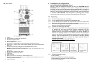
2.1. System Overview
This On-Line UPS protects computers, servers, internetworking, and
telecommunications equipment from blackouts, brownouts, overvoltages, and
surges. This On-Line UPS converts the input AC to DC and then back to a
True Sine Wave AC output. The True Sine Wave output is regulated within
2% of the nominal output voltage. The Power Factor Correction (PFC)
circuitry corrects the input power factor to within 98% of unity and blocks the
load generated harmonic distortion from getting back on the input AC line.
This On-Line UPS provides a continuous true sine wave output with zero
transfer time and great regulation to protect your mission critical equipment.
The UPS will quietly and confidently protect your system from power
anomalies.
2.2. General Characteristics
2.2.1 True On-Line architecture continuously supplies your critical equipment with
a stable, regulated, transient-free, pure sine wave AC Output Power.
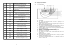
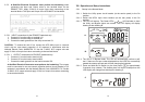
2.2.2 The multi-functional LCD/LED panel will display various states of the UPS.
The LED display will show the UPS working status, Utility Status and UPS
Abnormal status. The LCD display will show the Input/Output voltage,
frequency, load status, internal temperature, and faults.
2.2.3 The digital control circuit enhances the ability of the UPS for remote control
and monitoring.
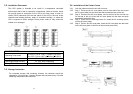
2.2.4 These UPS systems can be used in a Parallel Redundant application. To
operate these UPS systems in the Parallel Redundant mode requires the
Parallel Redundant kit. Contact your local distributor for more information
concerning the Parallel Redundant operation.
2.2.5 Maintenance Bypass Switch — which reduces down time for maintenance.
2.2.6 The DC-start function allows the start-up of UPS when there is no utility
power available.
2.2.7 This UPS system has the Independent Battery Bypass function. The
Independent Battery Bypass function allows the UPS system to provide a
stable, regulated, transient-free pure sine wave AC output power even
when the batteries are weak or dead.
2.2.8 The battery management circuit analyses the battery discharging status to
adjust the battery cut-off point and extend the life of batteries.
5
2.2.9 The temperature-controlled fans will extend the life of the fans and reduce
the annoying noise caused by fans.
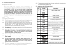
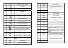
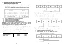
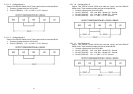
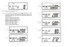
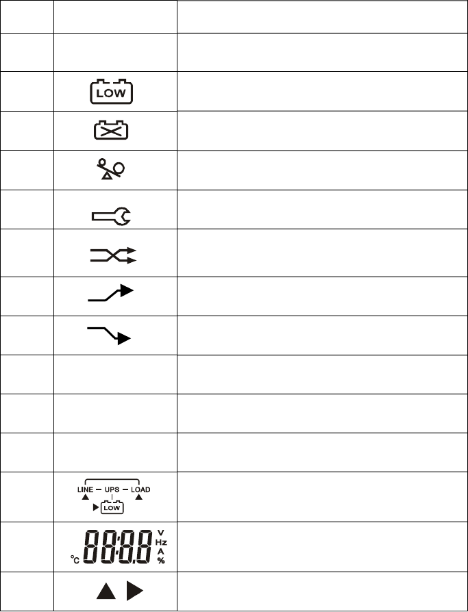
2.3. Symbols on the LCD Display Panel
Item Symbol Description
1
LINE
Utility or Bypass Source
2
Battery Low
3
Battery Abnormal
4
Output Overload
5
UPS working in specified mode
6
A Blackout Transfer occurred in UPS Output
7
Bypass Input Abnormal, UPS fails to transfer
to Bypass, Bypass Abnormal at ECO mode
8
Utility Input Abnormal
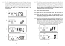
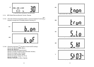
9
OFF
UPS Shutoff
10
BPS
Bypass Mode
11
LINE OFF UPS Abnormal Lock
12
UPS Flow Chart
13
4 Digits Measurement Display
14
Indicate the item desired to be measured