


8
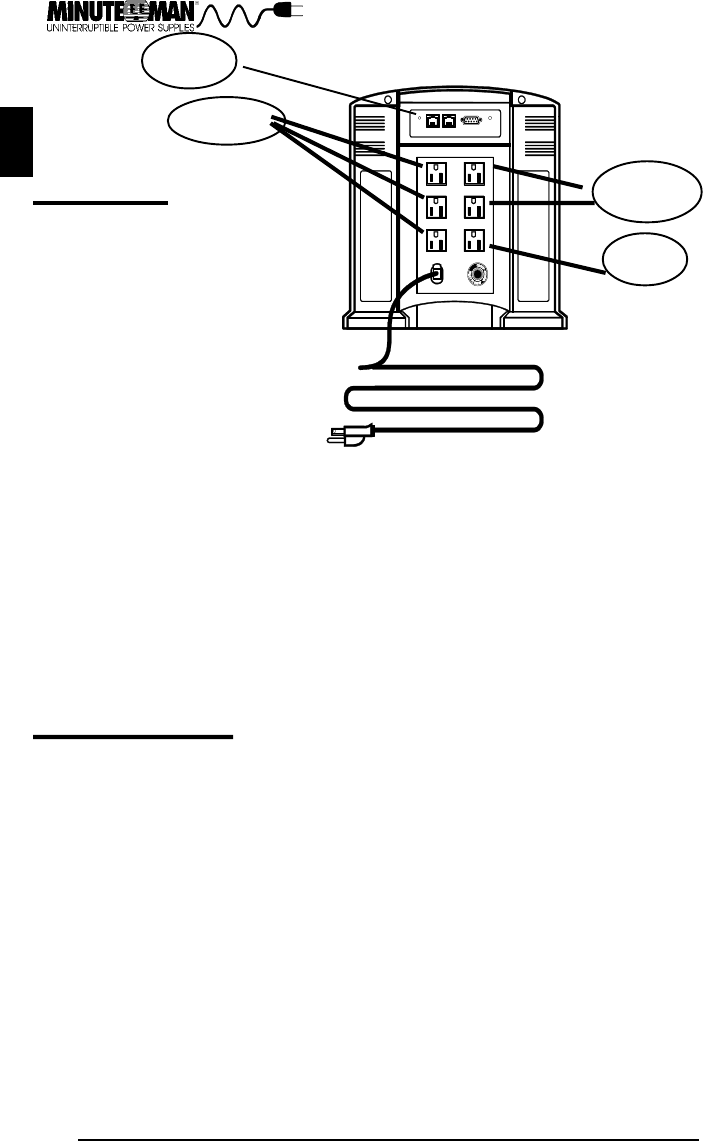
SWITCH
Surge only
Battery Backup
USER NOTES
English
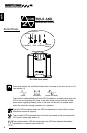
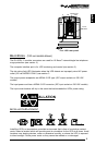
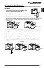
Rear Panel Switch Functions
During normal AC operation the rear panel
switch may be used to change the low
voltage transfer level. This voltage is the
voltage at which the unit switches from
normal operation to battery mode operation.
The transfer point is changed by pressing
and holding the switch until the switch
level desired is achieved. The factory
default level is 85 VAC
(international version is 170VAC).
1) Press and hold the switch until the unit sounds the audible alarm one time to change the
level to 80 VAC (160vac).
2) Press and hold the switch until the unit sounds the audible alarm twice sequentially to
change the level to 75 VAC (150VAC).
3) Press and hold the switch until the unit sounds the audible alarm three times sequentially
to reset to default setting.
While operating in the battery backup mode, the rear panel switch may be used to silence
the audible alarm. Press and hold the switch until the unit sounds the audible alarm once to
silence the audible alarm. The audible will reset and provide an alarm if the unit batteries are
nearing depletion. This is referred to as the low battery warning alarm. When utility power
returns and the unit switches to normal AC mode, the audible alarm will reset automatically
to provide a warning at the next power failure.
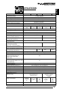
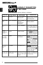
COMMUNICATIONS PORT
English
Battery Backup
The communications port is a standard DB9 female with both RS232 and simulated contact
closure capability. The Pro series units will poll the port and activate the port for RS232 or
contact closure in accordance with the type of cable it finds connected to the port. To
change the port configuration requires the unit be turned off and restarted with the desired
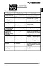
cable connected. The pinout for the port is depicted per the chart below.
Pin 1: Not used
Pin 2: /TXD
Pin 3: /RXD and receive ups shutdown command
Pin 4: Simulated contact closure AC fail, NO
Pin 5: Ground
Pin 6: Simulated contact closure low battery warning, NO
Pin 7: Simulated contact closure AC fail, NC
Pin 8: AC fail signal (high to low signal)
Pin 9: Instant off ( pull and hold this pin low to turn off output receptacles)