


MITSUBISHI ELECTRIC 2033C SERIES UPS
MITSUBISHI
ELECTRIC
2033C SERIES UPS
OWNERS / TECHNICAL MANUAL
Page Number:
1-12
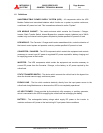
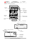
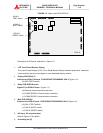
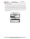
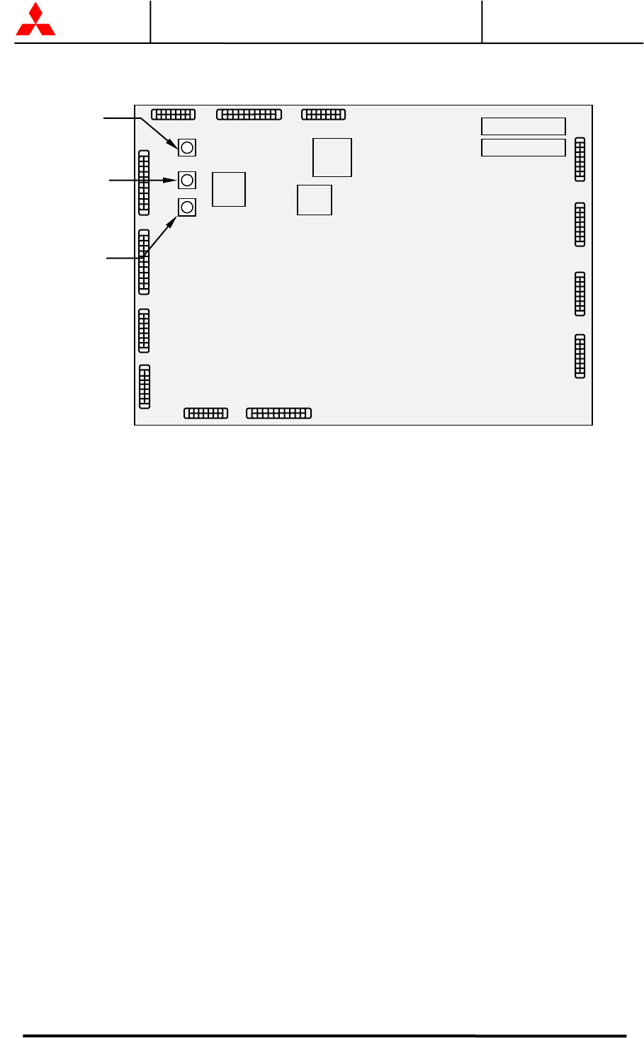
FIGURE 1.8 Main control PCB UPFR-K
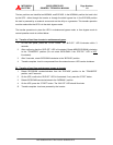
Description of UPS parts, referred to in Figure 1.5:
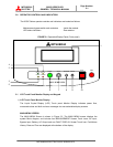
1. LCD Touch Panel Monitor Display
The Liquid Crystal Display (LCD) Touch Panel Monitor Display indicates power flow, measured
values and fault and error messages via user selectable display screens.
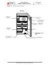
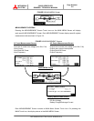
2. Display PCB DPAU-72
Switches on DPAU-72 board : FOR SERVICE PERSONNEL ONLY (Figure 1.6):
- (8) SW5 (TEST switch)
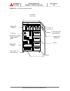
3. Relay PCB RYDR-X board
Signal I/F on RYDR-X board : (Figure 1.7):
- (9) External contact signal terminal block
- (10) CN62 (RS232C communication connector)
- (11) CN64 (RS232C communication connector)
4. Main PCB UPFR-K
Switches on UPFR-K board : FOR SERVICE PERSONNEL ONLY (Figure 1.8):
- (8) SW11 (TEST switch)
- (12) SW13 (BOOT switch).
- (13) SW14 (RESET switch)
5. AC input, AC output terminal
Refer to Figure 3.3 for details
6. Grounding bar (E)
UPFR-K
12.SW13
BOOT switch
13.SW14
RESET switch
8.SW11
TEST switch