


MITSUBISHI ELECTRIC 2033C SERIES UPS
MITSUBISHI
ELECTRIC
2033C SERIES UPS
OWNERS / TECHNICAL MANUAL
Page Number:
iv
List of Figures
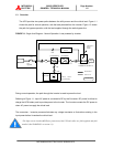
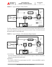
Figure 1.1 Single Line Diagram-Normal Operation ....................................... 1-5
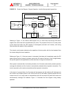
Figure 1.2 Single Line Diagram-Bypass Operation....................................... 1-6
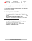
Figure 1.3 Single Line Diagram-Battery Operation ....................................... 1-7
Figure 1.4 Single Line Diagram - UPS on Maintenance Bypass Operation. . 1-7
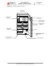
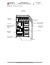
Figure 1.5a UPS Parts Location (7.5-20kVA) ................................................. 1-9
Figure 1.5b UPS Parts Location (30kVA) ....................................................... 1-10
Figure 1.5c UPS Parts Location (40,50kVA) .................................................. 1-11
Figure 1.6 Display PCB DPAU-72 ............................................................... 1-11
Figure 1.7 External I/F PCB RYDR-X .......................................................... 1-11
Figure 1.8 Main Control PCB UPFR-K.......................................................... 1-12
Figure 2.1 Operation/Display Panel ............................................................. 2-1
Figure 2.2 MAIN MENU Screen ................................................................... 2-2
Figure 2.3 MEASURMENT Screens ............................................................ 2-2
Figure 2.4 DATE&CLOCK SETUP Screen .................................................. 2-4
Figure 2.5 External Signal Terminal Block ................................................... 2-5
Figure 2.6 External Signal Terminal Block ................................................... 2-5
Figure 2.7 Control Wiring for External Contacts ........................................... 2-6
Figure 2.8 Remote "Start" Contact Connections........................................... 2-7
Figure 2.9 External communication connector.............................................. 2-8
Figure 3.1 Handling ..................................................................................... 3-1
Figure 3.2 UPS Terminal Designation .......................................................... 3-5
Figure 3.3 Input / Output Power Terminals (7.5-20kVA) -............................. 3-6
Figure 3.4 Input / Output Power Terminals (30kVA) ................................... 3-7
Figure 3.5 Input / Output Power Terminals (40,50kVA) ............................... 3-8
Figure 3.6 EPO Button ................................................................................. 3-9