


MITSUBISHI ELECTRIC 2033C SERIES UPS
MITSUBISHI
ELECTRIC
2033C SERIES UPS
OWNERS / TECHNICAL MANUAL
Page Number:
2-1
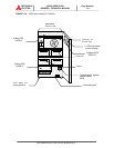
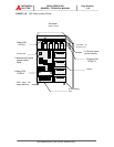
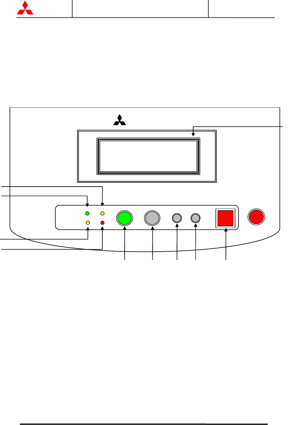
2.0 OPERATOR CONTROLS AND INDICATORS
The 2033C Series operator controls and indicators are located as follows:
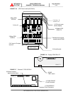
Maintenance bypass switch and contactors : Inside the module
UPS status indicators : Door exterior
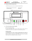
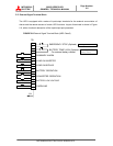
FIGURE 2.1 Operation/Display Panel (Front panel)
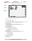
2.1 LCD Touch Panel Monitor Display and Keypad
1) LCD Touch Panel Monitor Display
The Liquid Crystal Display (LCD) Touch panel Monitor Display indicates power flow,
measured values and fault and error messages via user selectable display screens.
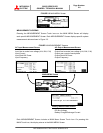
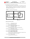
MAIN MENU SCREEN
The MAIN MENU Screen is shown in Figure 2.2. The MAIN MENU screen displays the
system Mimic diagram, and includes four MEASUREMENT Screen Touch icons: AC Input,
Bypass Input, Battery, AC Output and one FAULT DISPLAY Screen Touch Icon: Fault/Alarm
History. Date and Time are displayed at the bottom of the display.
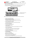
2033C SERIES UPS
MBP
MITSUBISHI
INV OP. BYP OP.
FAILUREBAT OP.
START STOP
SILENCE CLEAR
EPO
2
3
4
5
6
7
8
9
10
1