


MITSUBISHI ELECTRIC 9800A SERIES UPS
MITSUBISHI
ELECTRIC
9800A SERIES UPS
OWNERS / TECHNICAL MANUAL
Page Number:
1-12
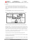
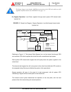
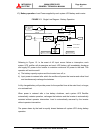
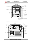
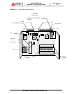
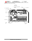
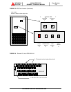
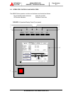
Description of Figures 1.4, 1.5, and 1.6:
1. CPM - Circuit protector for control power supply.
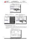
2. Switches on IFGR-G board : FOR SERVICE PERSONNEL ONLY (FIGURE 1.6):
- (4) External contact signal terminal
- (5) RS232C communication connector
3. Grounding bar (G)
4. External contact signal terminal block - Terminal block to connect contact signal
input/output lines to and from the external devices. Refer to Figure 2.15 section 2.4 for
details.
5. RS232C communication connector - Refer to Figure 2.18 section 2.5 for details.
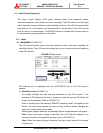
6. Inverter start switch - This switch is used to transfer the UPS from static bypass to
inverter during maintenance purposes. Transfers will lock-out if the bypass voltage is
more than +12%,-12% of nominal.
* Uninterrupted switching is made at the time of synchronous operation. Switching is impossible at
the time of asynchronous operation.
7. “INVERTER STOP” switch - This switch is used to transfer the UPS from inverter to
static bypass during maintenance purposes. Do not operate it under normal operation.
Transfers will lock-out if the bypass voltage is more than +12%,-12% of nominal.
* Uninterrupted switching is made at the time of synchronous operation. Switching is impossible at
the time of asynchronous operation.
8. “FAULT RESET” switch (FOR SERVICE PERSONNEL ONLY) - This switch resets errors
resulting from alarm conditions. (Do not operate this switch while inverter and converter are
in operation.)
9. Maintenance (Set) button (FOR SERVICE PERSONNEL ONLY) - This switch sets the
UPS menu parameters.
10. “Test mode” switch (FOR SERVICE PERSONNEL ONLY) - This switch changes system
operation to the test-mode. (This switch should not be operated by personnel other than
an Authorized Service Engineer).
11. “BOOT” switch (FOR SERVICE PERSONNEL ONLY) - This switch boots the processor
in the main control circuit resulting from alarm conditions. (Do not operate this switch
while inverter and converter are in operation).