MITSUBISHI ELECTRIC 9800A SERIES UPS
MITSUBISHI
ELECTRIC
9800A SERIES UPS
OWNERS / TECHNICAL MANUAL
Page Number:
2-10
A) Output Contacts (for external alarm annunciation)
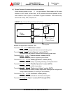
Output contacts consist of form “A” dry type contacts. Rated capacity of all output
contacts is NEC Class2 (30Vdc/1Adc). All dry contacts should be operated at their
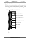
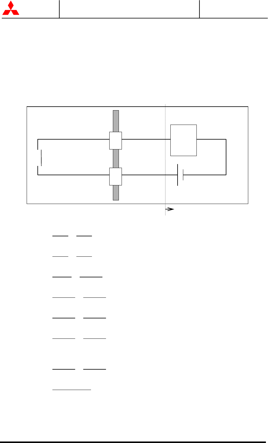
rated values or lower. Figure 2.16 illustrates a typical installation. The external relay
can also be a lamp, LED, computer, etc.
FIGURE 2.16 Control Wiring for External Contacts
Terminal
UPS Cabinet
External to UPS
Cabinet
Relay
Coil
N
EC Class 2
Power Source
Relay
Contact
Terminal
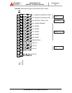
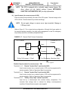
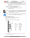
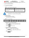
Details of output alarm contacts : TN1
Terminals 1 to 2
, 3 to 4 "UPS failure" contact
Activated when a major fault has occurred with the system.
Terminals 5 to 6
, 7 to 8 "Load on Bypass" contact (OUT1)
Activated when the power is supplied from the static bypass input.
Terminals 9 to 10
, 11 to 12 "Load on Inverter" contact (OUT2)
Activated when the power is supplied by the inverter.
Terminals 13 to 14
, 15 to 16 "Battery Operation" contact (OUT3)
Activated when the battery is operating following an AC power failure.
Terminals 17 to 18
, 19 to 20 "Rectifier Operation" contact (OUT4)
Activated when the rectifier is operating.
Terminals 21 to 22
, 23 to 24 "Battery Low Voltage" contact (OUT5)
Activated when the battery voltage drops below discharge end voltage level
during inverter operation (i.e. During AC fail condition).
Terminals 25 to 26
, 27 to 28 "Overload" contact (OUT6)
Activated when an overload has occurred to the system.
Terminals 29 through 40
"Spare" contact (OUT7 through OUT9)
User supplied


