


MITSUBISHI ELECTRIC 9800A SERIES UPS
MITSUBISHI
ELECTRIC
9800A SERIES UPS
OWNERS / TECHNICAL MANUAL
Page Number:
iv
List of Figures
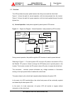
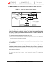
Figure 1.1 Single Line Diagram-Normal Operation.................................................. 1-5
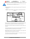
Figure 1.2 Single Line Diagram-Bypass Operation.................................................. 1-6
Figure 1.3 Single Line Diagram-Battery Operation .................................................. 1-7
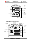
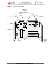
Figure 1.4 UPS Parts Location ................................................................................ 1-8
Figure 1.5 UPS Parts Location (Continued)............................................................. 1-10
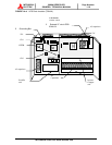
Figure 1.6 External I/F circuit PCB IOAU-04 .......................................................... 1-10
Figure 2.1 Operation/Display Panel......................................................................... 2-1
Figure 2.2 Main Screen ........................................................................................... 2-3
Figure 2.3 Start/Stop Screen ................................................................................... 2-4
Figure 2.4 PIN Protection Screen ............................................................................ 2-4
Figure 2.5 Bypass Voltage Abnormal Message Screen........................................... 2-4
Figure 2.6 Measurement Screen ............................................................................. 2-4
Figure 2.7 Setup Screen.......................................................................................... 2-5
Figure 2.8 Log Select Screen .................................................................................. 2-5
Figure 2.9 Event Log Screen ................................................................................... 2-5
Figure 2.10 Battery Log Screen ............................................................................... 2-6
Figure 2.11 Main Screen (Battery Operation) .......................................................... 2-6
Figure 2.12 Measurement Screen (Battery Operation).............................................. 2-6
Figure 2.13 Main Screen (Fault Indication) .............................................................. 2-7
Figure 2.14 Message Screen ................................................................................... 2-7
Figure 2.15 External Signal Terminal Block............................................................... 2-8
Figure 2.16 Control Wiring for External Contacts ...................................................... 2-10
Figure 2.17 Remote "Start" Contact Connections...................................................... 2-11
Figure 2.18 External communication connector......................................................... 2-12
Figure 3.1 UPS Terminal Designation .................................................................... 3-6
Figure 3.2 Diagram of input/output bus bars and terminal blocks .......................... 3-7
Figure 3.3 Diagram of Rectifier Cabinet & Inverter Cabinet Inter-connect ............. 3-19
Figure 3.4 Diagram of Power and Control Wire Connect (Parallel Connection) ...... 3-21
Figure 3.5 Operation Procedures: Start Up/Shut Down Procedure.......................... 3-24