


F940GOT-SWD-E/LWD-E Installation, Wiring and General Specifications 2.
2-37
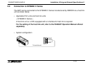
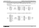
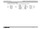
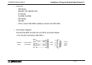
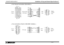
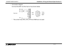
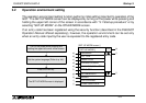
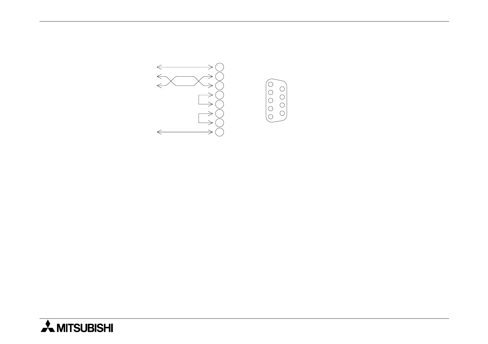
• Connection diagram
Connect the GOT and the host unit as shown below.
* The control lines RTS, CTS, DTR and DSR are not used.
D-sub
(male)
9-pin
GOT
side
Host side
5
4
3
2
1
9
8
7
6
SD
RD
FG
SG
1
2
3
7
8
6
4
5